


C-6
Cisco ME 3400 Ethernet Access Switch Hardware Installation Guide
OL-7677-04
Appendix C Connecting to DC Power
Wiring the DC-Input Power Source
Complete these steps:
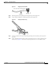
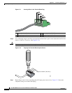
Step 1 Remove all paint or oxidation from the rack at the point of the grounding connection.
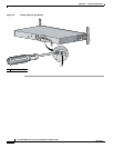
Step 2 Use a 3/16-inch flat-head screwdriver to loosen the grounding screw on the rack.
Step 3 Connect the wire to a ring lug (large enough for the rack screw to fit through).
Step 4 Use a 3/16-inch flat-head screwdriver and the screw to attach the ring lug to the rack.
Step 5 Tighten the grounding screw on the rack over the ring lug.
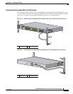
Repeat these steps for each switch being installed.
Wiring the DC-Input Power Source
Before you wire the DC-input power source, review the warnings in this section and this information:
If the switch software detects that the circuit boards are not receiving power from an internal power
supply, the software sends a message like this to the console:
00:06:54: %POWER_SUPPLIES-3-PWR_FAIL: Power supply 2 is not functioning
00:06:54: %PLATFORM_ENV-1-DUAL_PWR: Faulty internal power supply 2 detected
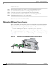
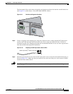
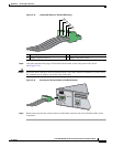
This message means that an internal power supply is not providing power. To receive this alert if power
fails on the ME 3400G-12CS-DC switch with two power feeds, we recommend that you connect one feed
to the left DC power terminal block and the other to the right DC power terminal block. (See the example
in Figure C-6.)
Figure C-6 Connecting Separate Feeds to Each of the DC Power Terminal Blocks
1 Primary power feed 2 Secondary (redundant) power feed
CONSOLE
S
Y
S
T
E
M
INPUT -36 – -72 V
CURRENT 2 – 1A
A
B
+
+
INPUT -36 – -72 V
CURRENT 2 – 1A
A
B
+
+
PS 1
PS 2
191863
1
2