


1-11
Cisco ME 3400 Ethernet Access Switch Hardware Installation Guide
OL-7677-04
Chapter 1 Product Overview
Front Panel Description
Dual-Purpose Port LEDs
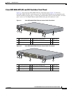
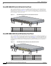
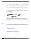
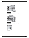
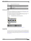
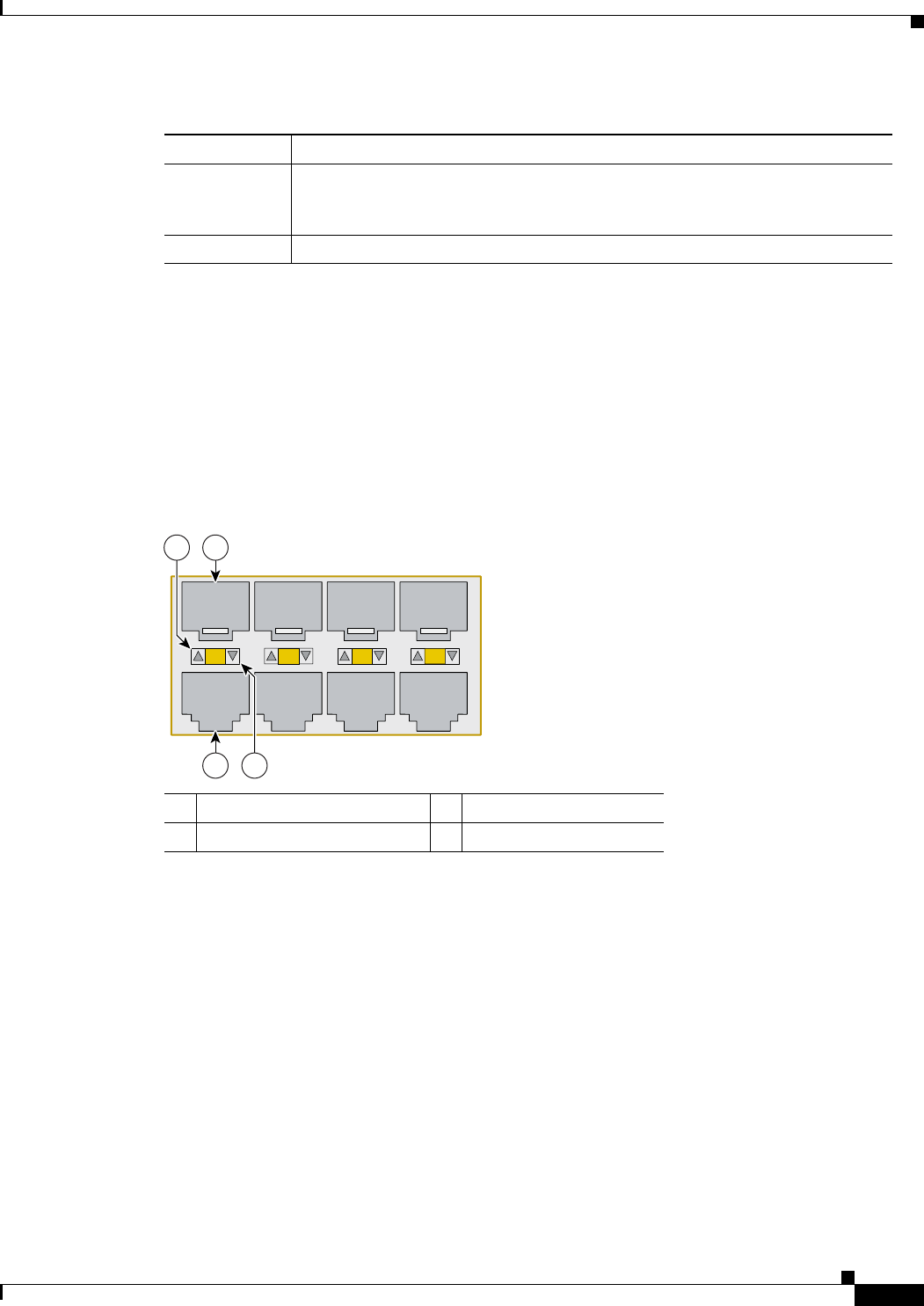
The LEDs on the Cisco ME 3400G-12CS switch dual-purpose ports, as shown in Figure 1-12, show
which is connected: either an RJ-45 connector or an SFP module. The Cisco ME3400G-2CS switch
dual-purpose ports are similar to those shown in this section.
You can configure each dual-purpose port as either 10/100/1000 ports that use RJ-45 connectors or as
SFP module ports, but not both types at the same time. The LEDs show how the port is being
used—either as an RJ-45 Ethernet port or as an SFP module.
Figure 1-12 Cisco ME 3400G-12CS Switch Dual-Purpose Port LEDs
The LED colors have the same meanings as described in Table 1-3 on page 1-10.
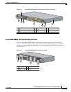
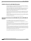
Console Port
You can connect the switch to a PC by means of the console port and an RJ-45-to-DB-9 female cable.
If you want to connect the switch console port to a terminal, you need to provide an RJ-45-to-DB-25
female DTE adapter. You can order a kit (part number ACS-DSBUASYN=) containing that adapter from
Cisco. For console port and adapter pinout information, see the “Connector and Cable Specifications”
section on page A-1.
Alternating
green-amber
Link fault. Error frames can affect connectivity, and errors such as excessive
collisions, CRC errors, and alignment and jabber errors are monitored for a
link-fault indication.
Amber Port is disabled.
Table 1-3 Meaning of Port LED Colors (continued)
LED Color Meaning
1 SFP module port in-use LED 3 RJ-45 port in-use LED
2 SFP module slot 4 RJ-45 connector
1
2
3
4
4
2
157516
3
1