


C-7
Cisco ME 3400 Ethernet Access Switch Hardware Installation Guide
OL-7677-04
Appendix C Connecting to DC Power
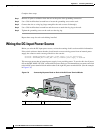
Wiring the DC-Input Power Source
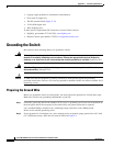
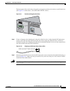
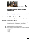
If you want to receive an alert if an external power supply fails, do not connect feeds to one terminal
block and from there connect feeds to the second terminal block. (See the example in Figure C-7.) This
configuration provides redundant power, and the switch continues to operate if one of the external power
supplies fails. However, the software does not send a message to you that an internal power supply has
failed.
Figure C-7 Connecting Feeds from One Terminal Block to the Second Terminal Block
Cisco ME 3400-24TS Switches
This warning only applies to Cisco ME 3400-24TS switches:
Warning
This product relies on the building’s installation for short-circuit (overcurrent) protection. Ensure that
the protective device is rated not greater than:
5 A
Statement 1005
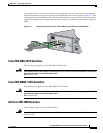
Cisco ME 3400G-12CS Switches
This warning only applies to Cisco ME 3400G-12CS switches:
Warning
This product relies on the building’s installation for short-circuit (overcurrent) protection. Ensure that
the protective device is rated not greater than:
6 A
Statement 1005
All Cisco ME 3400 Switches
These warnings apply to all Cisco ME switches:
Warning
A readily accessible two-poled disconnect device must be incorporated in the fixed wiring.
Statement 1022
CONSOLE
S
Y
S
T
E
M
INPUT -36 – -72 V
CURRENT 2 – 1A
A
B
+
+
INPUT -36 – -72 V
CURRENT 2 – 1A
A
B
+
+
PS 1
PS 2
191867