


1-8
Cisco ME 3400 Ethernet Access Switch Hardware Installation Guide
OL-7677-04
Chapter 1 Product Overview
Front Panel Description
Use only Cisco SFP modules on your switch. Each SFP module has an internal serial electrically
erasable programmable read-only memory (EEPROM) that is encoded with security information. This
encoding provides a way for Cisco to identify the module and to ensure that it meets the performance,
quality, and interoperability requirements for the device.
For information about Cisco SFP modules, see the documentation at this URL:
http://www.cisco.com/en/US/products/hw/modules/ps5455/tsd_products_support_series_home.html
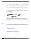
SFP Module Patch Cable
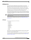
The Cisco ME switch supports the SFP module patch cable, a 0.5-meter, copper, passive cable with
SFP module connectors at each end (see Figure 1-7). The patch cable connects two Cisco ME switches
in a cascaded configuration.
Figure 1-7 SFP Module Patch Cable
See the “Inserting and Removing the SFP Module Patch Cable” section on page 2-19 for more
information about using the SFP module patch cable.
On the Cisco ME-3400-24FS-A switch, only the Gigabit Ethernet uplink ports support the SFP module
patch cable.
You can order the SFP module patch cable (part number CAB-SFP-50CM=).
LEDs
You can use the switch System and port LEDs to monitor switch activity and performance. The LEDs
are described in these sections:
• System LED, page 1-8
• Power Supply LEDs (Only Cisco ME 3400G-12CS Switches), page 1-10
• Port LEDs, page 1-10
• Dual-Purpose Port LEDs, page 1-11
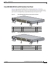
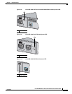
System LED
These illustrations show the location of the System LED:
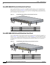
• Figure 1-8 on page 1-9, Cisco ME 3400-24TS and Cisco ME 3400-24FS Switches
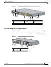
• Figure 1-9 on page 1-9, Cisco ME 3400-12CS Switch
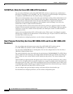
• Figure 1-10 on page 1-9, Cisco ME 3400G-2CS Switch
126809