


C-2
Cisco ME 3400 Ethernet Access Switch Hardware Installation Guide
OL-7677-04
Appendix C Connecting to DC Power
Grounding the Switch
• 6-gauge copper ground wire (insulated or noninsulated)
• Four leads of copper wire
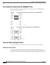
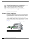
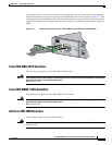
• The DC terminal block (Figure C-13)
• 12-28 AWG copper wire
• Wire-stripping tools
To order spare or replacement DC connectors, use one of these sources:
• Digi-Key, part number 277-1013-ND, www.digikey.com
• Phoenix Contact, part number 1757035, www.phoenixcontact.com
Grounding the Switch
Review these safety warnings before you ground the switch.
Warning
This equipment must be grounded. Never defeat the ground conductor or operate the equipment in the
absence of a suitably installed ground conductor. Contact the appropriate electrical inspection
authority or an electrician if you are uncertain that suitable grounding is available.
Statement 1024
Warning
When installing or replacing the unit, the ground connection must always be made first and
disconnected last.
Statement 1046
Caution To make sure that the equipment is reliably connected to earth ground, follow the grounding
procedure instructions, and use a UL-listed lug suitable for number-6 AWG wire and two number-10-32
ground-lug screws.
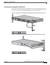
Preparing the Ground Wire
Before you ground the switch to earth ground, you must prepare the ground wire. Follow these steps.
Make sure to follow any grounding requirements at your site.
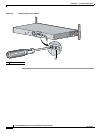
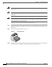
Step 1 Locate the ground lug and the two number-10-32 screws. A ground lug and screws are located both on
the front panel and on the rear panel of the switch. Only one ground connection is required.
Use a standard Phillips screwdriver or a ratcheting torque screwdriver with a Phillips head.
Set the screws and the ground lug aside.
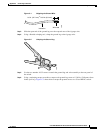
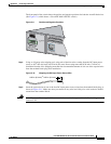
Step 2 If your ground wire is insulated, use a wire stripping tool to strip the 6-gauge ground wire to 0.5 inch
(12.7 millimeter [mm]) ± 0.02 inch (0.5 mm) as shown in Figure C-1.