


4-14
User Guide for the Cisco Network Analysis Module (NAM) Traffic Analyzer, 5.0
OL-22617-01
Chapter 4 Capturing and Decoding Packet Data
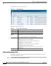
Sessions
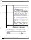
Step 7 Click Submit.
IP
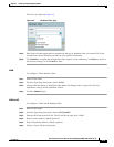
To configure an IP hardware filter:
Step 1 Enter a Filter Name.
Step 2 From the Type drop-down menu, choose IP.
Step 3 Enter a Source Address / Mask (optional).
Step 4 Enter a Destination Address / Mask (optional).
Step 5 Choose a Layer 4 IP Protocol (optional)
Step 6 Click Submit.
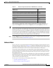
IP and TCP/UDP
To configure an IP and TCP/UDP hardware filter:
Step 1 Enter a Filter Name.
Step 2 From the Type drop-down menu, choose IP and TCP/UDP
Step 3 Enter a Source Address / Mask (optional).
Step 4 Enter a Destination Address / Mask (optional).
Step 5 Choose an IP Protocol, either TCP or UDP.
Step 6 Enter a TCP/UDP Source Port (optional).
Step 7 Enter a TCP/UDP Destination Port (optional).
Step 8 Click Submit.
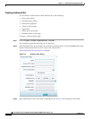
IP and Payload Data
To configure an IP and Payload Data hardware filter:
Step 1 Enter a Filter Name.
Step 2 From the Type drop-down menu, choose IP and Payload Data.
Step 3 Enter a Source Address / Mask (optional).
Step 4 Enter a Destination Address / Mask (optional).
Step 5 Choose an IP Protocol, either TCP or UDP.
Step 6 Enter the values for Payload Data:
• Enter an Offset from 1-1023. The offset is relative to the beginning of the payload (Layer 5).
• Enter a Value of up to four bytes (eight hex characters).