


Chapter 3 Installing the Router
Connecting to the Console and Auxiliary Ports
3-24
Cisco 12006 and Cisco 12406 Router Installation and Configuration Guide
OL-11497-03
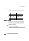
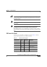
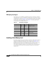
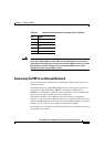
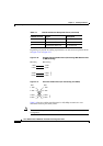
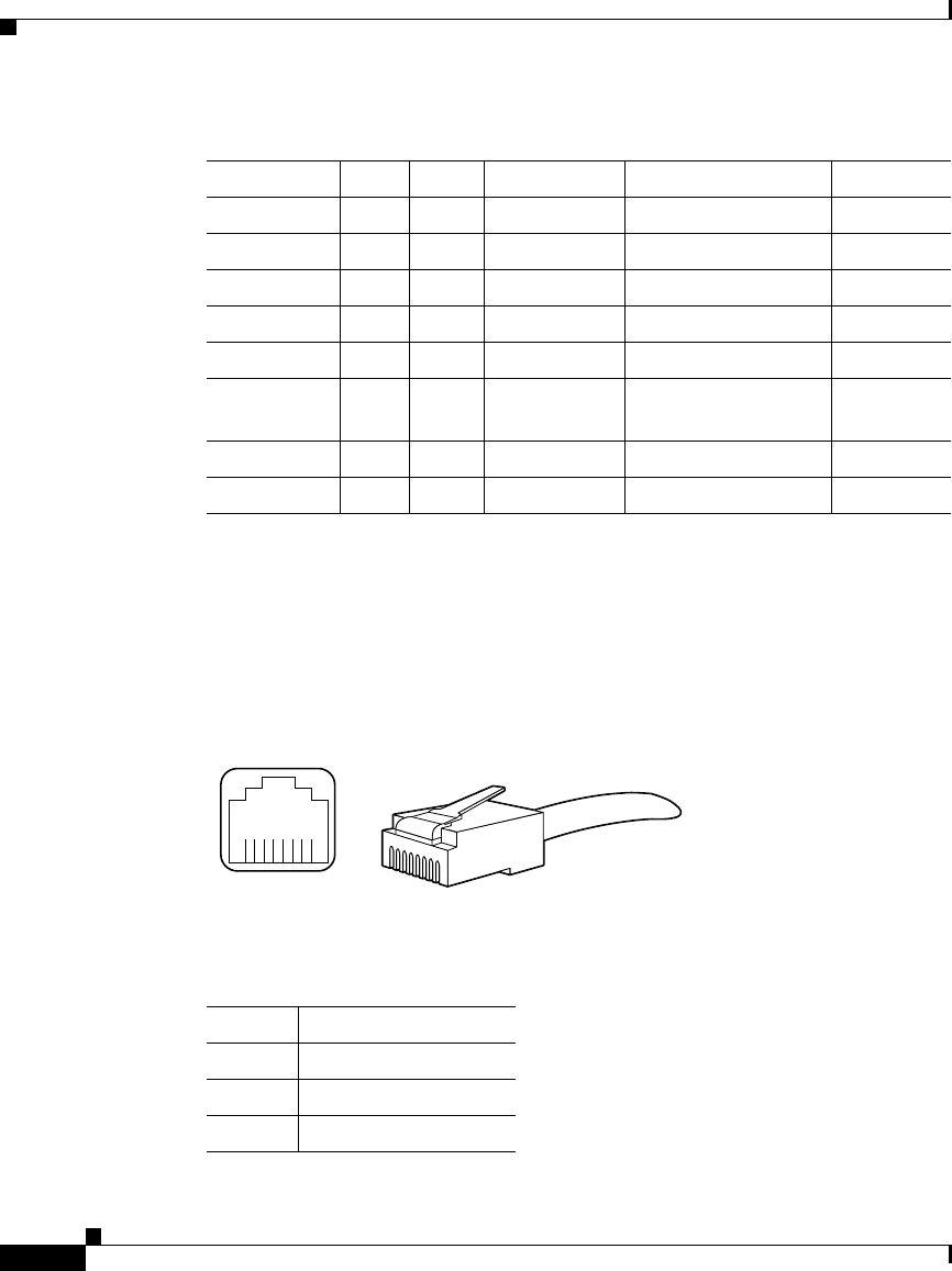
Figure 3-13 shows the pin configuration on the Ethernet RJ-45 receptacle on the
GRP. Table 3-6 lists the signal-to-pin correspondence for the Ethernet RJ-45
receptacle on the GRP.
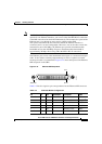
Figure 3-13 Ethernet RJ-45 Receptacle
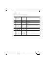
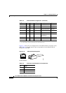
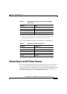
9 Yes – – Receive Clock Rx_CLK
10 Yes – – Receive Error Rx_ER
8 Yes – – Receive Data Valid Rx_DV
18 Yes – – Collision COL
19 Yes – – Carrier Sense CRS
2 – – Yes MII Data
Input/Output
MDIO
22 to 39 – – – Common Ground
1, 20, 21, 40 – – – +5.0 V V
1. Unlisted pins are not used.
2. Tx_CLK and Rx_CLK are provided by the external transceiver.
Table 3-5 Ethernet MII Pin Configuration (continued)
Pin
1
In Out Input/Output Description Code
Ta b l e 3-6 Ethernet RJ-45 Receptacle Pin Configuration
Pin Signal
1 TX+
2 TX–
3 RX+
H2936
8 7 6 5 4 3 2 1
RJ-45 connector