


6-11
Cisco 12006 and Cisco 12406 Router Installation and Configuration Guide
OL-11497-03
Chapter 6 Maintaining the Router
Removing and Replacing the Blower Module
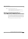
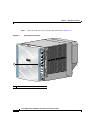
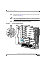
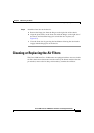
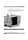
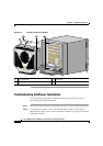
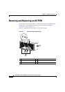
Step 2 Install the new blower module (Figure 6-6):
a. Position the alignment holes on the blower module with the guide pins at the
top of the chassis and on the PDU at the bottom of the chassis.
b. Slide the blower toward the chassis until it mates with the backplane
connector.
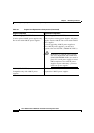
Caution Electrical and control line connections for the blower module and backplane
occur automatically when the connectors on the blower module and PDU mate.
To prevent damage to the blower module and PDU connectors, do not use
excessive force when installing the blower module against the rear of the chassis.
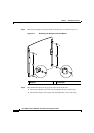
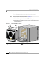
c. Tighten the four captive screws to secure the blower module to the chassis.
The (green) OK indicator should light. If the OK indicator does not light, see
the
“Troubleshooting the Blower Installation” section on page 6-12.
d. Lower the blower module handle to its operating position.