


6-41
Cisco 12006 and Cisco 12406 Router Installation and Configuration Guide
OL-11497-03
Chapter 6 Maintaining the Router
Removing and Replacing a DC PDU
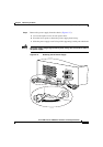
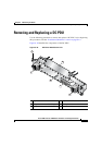
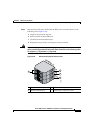
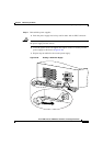
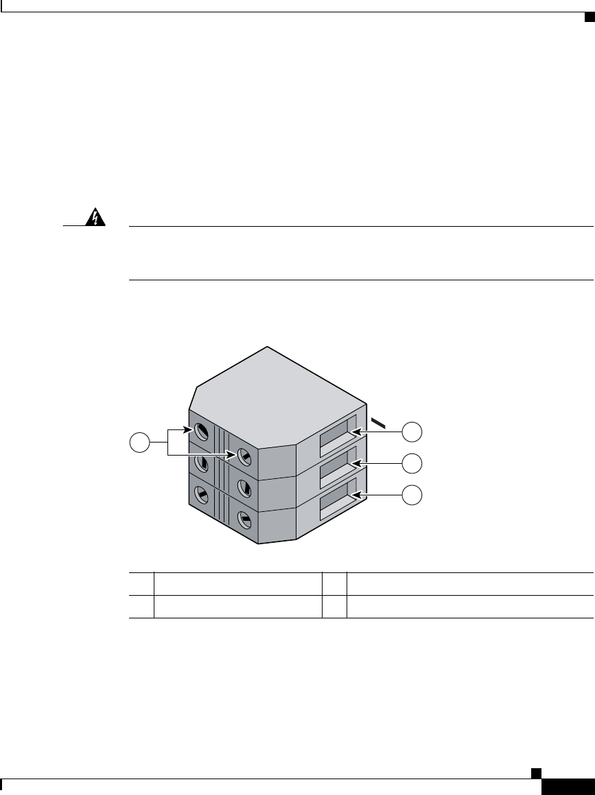
Step 5 Disconnect the DC power leads from the PDU power connector blocks in the
following order (
Figure 6-22):
a. Negative lead from the top port.
b. Positive lead from the middle port.
c. Ground lead from the bottom port.
d. Repeat these steps for the second power connector block.
Warning
To prevent injury and damage to the equipment, always remove the source DC
power leads and ground from the power shelf terminals in the following order:
(a) negative (–), (b) positive (+), (c) ground.
Figure 6-22 Disconnecting the DC Power Leads
1 Negative terminal port 3 Ground terminal port
2 Positive terminal port 4 Terminal port connector screws
57993
POWER A
+
GND
1
4
2
3