


Appendix A Technical Specifications
Specifications
A-6
Cisco 12006 and Cisco 12406 Router Installation and Configuration Guide
OL-11497-03
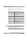
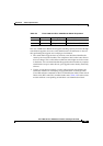
Alarm Card Alarm Relay Connector Specifications
The alarm card alarm relay connector is a standard DB-9 connector. The relay
interface is rated at max 2A, 60V, or 50VA, whichever is greater. The connector
pins and their definitions are shown in
Table A-5.
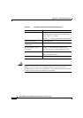
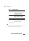
Router Performance Upgrades and Model Identification
The compliance information label on the side of the chassis also identifies the
Cisco 12000 Series Router by its model number. The model number indicates the
router is in the Cisco 12000 Series, the maximum switching capacity the router
supports, and the number of line card and RP slots in the chassis.
For example, the Cisco 12006 Router features 30 Gbps switching capacity in a
6-slot, 2.5-Gigabit per slot chassis, whereas the Cisco
12406 Router features
120
Gbps switching capacity in a 6-slot, 10-Gigabit per slot chassis. Table A-6
lists the Cisco 12006 and Cisco 12406 Routers and provides model comparison
information based on chassis slot counts, maximum switching capacity, and
switch fabric type.
Ta b l e A-5 Alarm Card Alarm Relay Contact Connector Pinout
Pin Name Definition
1 Critical_NO Critical, normally open contact
2 Critical_C Critical, common contact
3 Major_NO Major, normally open contact
4 Minor_NO Minor, normally open contact
5 Minor_C Minor, common contact
6 Critical_NC Critical, normally closed contact
7 Major_NC Major, normally closed contact
8 Major_C Major, common contact
9 Minor_NC Minor, normally closed contact