


5-11
Cisco 7600 Series Ethernet Services Plus Line Card Hardware Installation Guide
OL-16146-10
Chapter 5 Installing and Removing SFP and XFP Modules
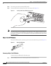
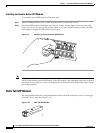
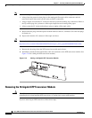
Removing and Installing XFP Modules
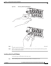
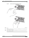
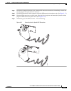
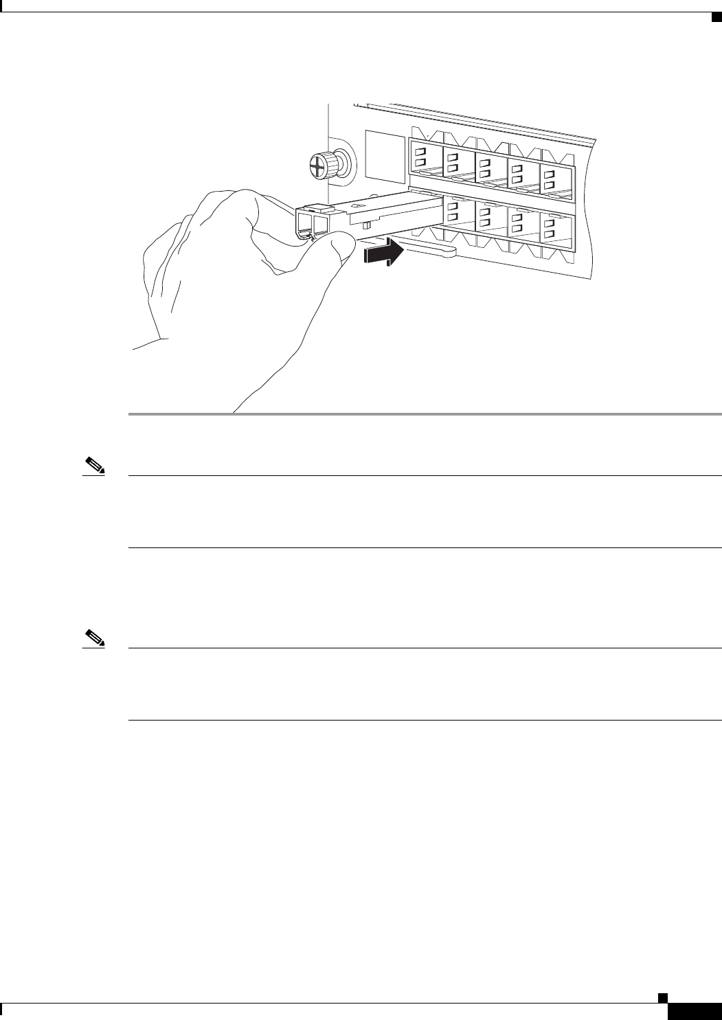
Figure 5-13 Installing a Slide Tab SFP Module
Note Verify that the SFP modules are completely seated and secured in their assigned receptacles on the line
card by firmly pushing on each SFP module. If the SFP module is not completely seated and secured in
the receptacle, you will hear a click as the triangular pin on the bottom of the SFP module snaps into the
hole in the receptacle.
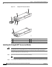
Removing and Installing XFP Modules
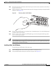
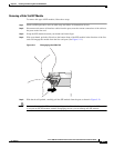
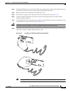
Note The dual LC connector on the XFP transceiver modules support network interface cables with either
Physical Contact (PC) or Ultra-Physical Contact (UPC) polished face types. The dual LC connector on
the XFP transceiver modules do not support network interface cables with an Angle Polished Connector
(APC) polished face type.
The 10-Gigabit XFP transceiver module is a hot-swappable I/O device that plugs into 10-Gigabit ports.
(See Figure 5-14.) The XFP transceiver module connects the electrical circuitry of the system with the
optical network.
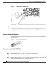
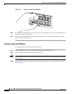
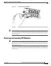
7600-ES+20G3CXL
ETHERNET SERVICES MODULE
S TATU S
EXT CLK
1
2
3
5
7
9
4
6
8
10
7600-ES+20G3CXL
S TATU S
EXT CLK
1
2
3
5
7
9
4
6
8
10
280869