


1-17
Cisco SFS 7024 InfiniBand Server Switch Hardware Users Guide
OL-8794-05
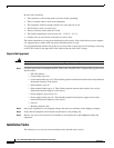
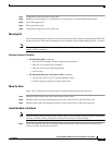
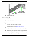
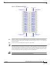
Figure 7 Install the Lower Mounting Bracket and Heyclip
Step 8 Install the heyclip to the rail assembly.
Step 9 If applicable, reinstall the chassis fascia(s).
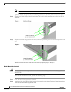
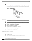
Installing the Switch Face Plate
To install the switch face plate(s):
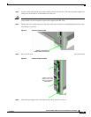
Step 1 On the switch fan side, insert the notches on the top of the fascia into the two slots on the chassis frame.
Snap the bottom of the faceplate in place.
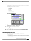
Installing the Spine and Leaf Modules
Note The purchased configuration for the SFS 7024 is shipped fully populated. Follow these steps when it
becomes necessary to install or replace spine modules and leaf modules.
Step 1 Remove the necessary spine modules, spine module blanks, leaf modules, and leaf module blanks. For
detailed instructions, please refer to the section
Removing a Module or Blank, page 1-19.
Note If the user is only adding additional modules, remove only the blank(s) for the slot(s) to be populated.
These will not be replaced.
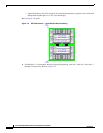
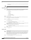
Step 1 When placing the spine modules and leaf modules into chassis slots, the following recommendations
apply:
a. Spine Modules — It is recommended that the spine module(s) be installed into:
–
Lower Hemisphere: Slot 1 for managed. For redundant management, populate slots 1 and 2 with
management-capable spines. Use slot 3 for unmanaged.
Install the lower rear
mounting bracket to the rail
assembly and chassis
Install the
heyclip here