


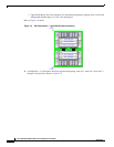

1-22
Cisco SFS 7024 InfiniBand Server Switch Hardware Users Guide
OL-8794-05
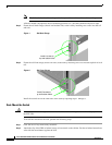
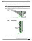
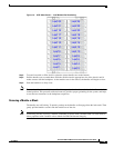
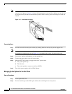
Note When handling IB connectors, make certain to remove the connectors by pulling on the center of the
lanyard only as shown in
Figure 1-12 below. Pulling abruptly on the lanyard, or pulling on only one side
of the lanyard will prevent the latch/unlatch operation from occurring, and could damage or break the
lanyard.
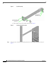
Figure 1-12 4X IB Cable Connector
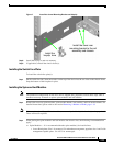
Connecting Power
Step 1 Provide strain relief for the power cable(s) by feeding them into the heyclips on the support rails.
Note Be certain that the power cords are firmly seated into the SFS 7024 AC power inlets. Depending upon
the purchased configuration, refer to Figure 1-11 to determine the correct AC power inlet to use.
Step 2 If necessary, replace the faceplates over the switch fans.
Step 3 Connect the power cables to an AC power outlet.
Step 4 When the SFS 7024 switch is plugged into an AC power outlet:
a. The system powers up.
b. The fans start.
c. The system performs a power-on self test (POST).
Step 5 The switch, power supply, and fan LEDs light up.
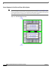
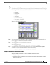
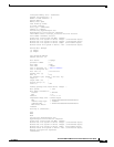
Bringing Up the System For the First Time
Start-up Procedures
Step 1 Power up the SFS 7024.
Step 2 From its flash image on the CMU spine module, the switch begins its boot process.