


7
Installation
24/48-Port 10/100 + 4-Port Gigabit Smart Switch with Resilient Clustering Technology and PoE
Chapter 3
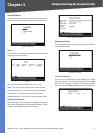
For a 1000 Mbps device:
Connect a Category 5e Ethernet network cable to
port G1, G2, G3, or G4 on the Switch.
For a 10/100 Mbps PoE device:
SLM248G4PS: Connect a Category 5e Ethernet
network cable to one of ports 1-12 or ports 25-36
on the Switch.
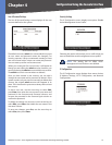
SLM224G4PS: Connect a Category 5e Ethernet
network cable to one of ports 1-6 or ports 13-18 on
the Switch.
Connect the other end of the network cable to a PC or
other network device.
Repeat steps 2 and 3 to connect additional devices.
If a 802.3af-compliant PoE device is connected to one
of the Switch’s PoE ports, the Switch will automatically
supply the required power to the device.
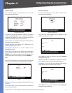
If you are using a miniGBIC port, then connect a
miniGBIC module to a miniGBIC port. For more detailed
instructions, refer to “Uplinking the Switch“.
Connect the supplied power cord to the Switch’s
power port, and plug the other end into an electrical
outlet. When connecting power, always use a surge
protector.
IMPORTANT: Make sure you use the power
cord that is supplied with the Switch. Use of a
different power cord could damage the Switch.
Power on the devices connected to the Switch. Each
active port’s corresponding LED will light up on the
Switch.
Uplinking the Switch
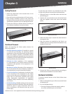
To uplink the Switch using a 1000 Mbps Ethernet port,
connect one end of a Cat 5e (or better) Ethernet network
cable to a Gigabit port, then connect the other end of the
cable into the peripheral device’s uplink port. MDI/MDIX
will automatically detect the speed and cable type.
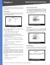
To uplink the Switch using the miniGBIC port, connect
a miniGBIC module to a miniGBIC port whose shared
Ethernet port is not being used (a miniGBIC port and its
shared Ethernet port cannot be used at the same time).
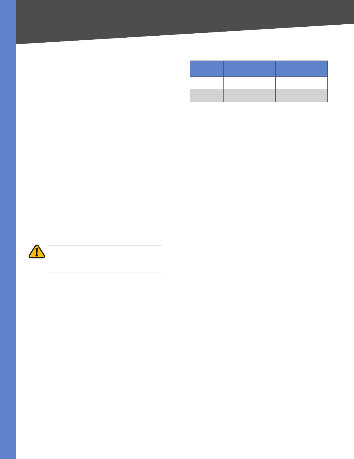
The following table shows which Ethernet ports are shared
with the miniGBIC ports.
•
•
•
3.
4.
5.
6.
7.
Ethernet Ports Shared with miniGBIC Ports
Switch
Port Shared with
miniGBIC1
Port Shared with
miniGBIC2
SLM248G4PS G3 G4
SLM224G4PS G3 G4
To establish a Gigabit Ethernet connection using a miniGBIC
port, you will need to install a MGBT1, MGBSX1, or MGBLH1
Gigabit expansion module and use Category 5e cabling or
fiber optic cabling.
To establish a Fast Ethernet connection using a miniGBIC
port, you will need to install a MFEFX1 (100BASE-FX) or
MFELX1 (100BASE-LX) 100SFP Transceiver and use fiber
optic cabling.
The hardware installation is complete. Proceed to
“Chapter 5: Configuration Using the Web-based Utility”,
for directions on how to set up the Switch.
Configuring Stack Mode
The SLM224G4PS and SLM248G4PS Switches can operate
in either standalone mode or stack mode. In standalone
mode, the switch operates independently of other
switches. In stack mode, multiple Stackable Switches are
connected together to effectively form a single switch.
The default operating mode is stack mode.
A Switch stack can contain any combination of
SLM224G4PS and SLM248G4PS units, with the following
limits:
SLM224G4PS only: Maximum of 6 units
SLM248G4PS only: Maximum of 4 units
SLM224G4PS and SLM248G4PS: Maximum of 192
10/100 ports (total among all switches)
Each switch in a stack is assigned a unique unit number.
These numbers indicate the switch’s status in the stack:
Unit 1: The switch is the Master unit. The master handles
the management functions for the entire stack.
Unit 2: The switch is the Backup Master unit. The backup
master automatically becomes the new master if the
master fails.
Unit 3, 4, 5, 6: The switch is a Slave unit. (Depending on
the switch models used, 5 and 6 may not be valid.)
The Switches are connected together using a pair of Gigabit
ports on each Switch: G1 and G2, G3 and G4, or miniGBIC1
and miniGBIC2. Linksys recommends using Gigabit ports
G1 and G2 (the default stacking ports). Connections are
made using Category 5e Ethernet network cables.
To set up a stack with six switches, follow these steps:
•
•
•
•
•
•