


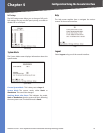


Chapter 5
Configuration Using the Web-based Utility
20
24/48-Port 10/100 + 4-Port Gigabit Smart Switch with Resilient Clustering Technology and PoE
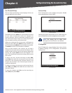
Recurring If daylight saving time has fixed start and
end dates, check this box and fill in these fields:
From Specify the day, week, month, and time
when daylight saving time will be enabled.
To Specify the day, week, month, and time when
dalight saving time will be disabled.
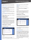
SNTP Servers
This is where you configure a Simple Network Time
Protocol (SNTP) server. SNTP servers are used to set the
system time and date automatically at set intervals.
Server1 The IP address of the primary SNTP server.
Server2 The IP address of a secondary SNTP server to be
accessed if the primary SNTP server is unavailable.
SNTP Polling Interval Enter the polling interval in
seconds. The valid range of values is 60 to 86400. The
default value is 1024 seconds (approx. 17 minutes).
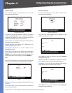
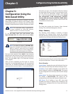
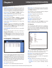
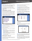
Setup > Stack Management
The Stack Management screen allows you to configure the
settings for the Switch stack.
Setup > Stack Management
Master Election If you want the system to assign the
master unit, keep the default setting, Automatically. If
you want to specify the master unit yourself, select Force
Master, then select unit 1 or 2 from the drop-down
menu.
NOTE: If unit 1 is the master unit and unit 1
becomes unavailable, unit 2 will immediately
become the master unit. If unit 1 becomes
available again within 10 minutes, unit 1 will be
restored as the master unit. If unit 1 becomes
available after 10 minutes, unit 2 will remain the
master unit. In this case, to restore unit 1 as the
master unit, set Master Election to specify unit 1
as the master unit, then reboot the stack.
•
•
•
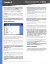
Stacking Ports After Reset This indicates which Gigabit
ports will be used for stacking when the system is reset.
Select either Copper Ports (default) or Combo Ports.
Unit No. After Reset This is used to change the unit
numbers of the switches in the stack when the system is
reset. To change a switch’s unit number, locate the unit in
the Unit No. column, then select the new unit number in
the Unit No. After Reset column.
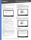
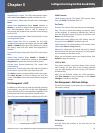
Port Management
The Port Management tab contains the Port Settings, Link
Aggregation, and LACP screens.
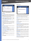
Port Management > Port Settings
The Port Settings screen displays the settings for the ports
on each switch in the system. The information on the Port
Settings screen is read-only. Click Detail to the right of a
port’s information to edit that port’s settings using the
Port Configuration screen. For detailed information on the
Port Configuration screen, refer to the “Port Configuration“
section.
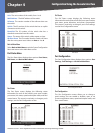
Port Management > Port Settings
The Port Settings screen displays the following information.
For more information on these settings, refer to the “Port
Configuration“ section.
Unit No. The unit (switch) that you are managing. The
default is the Master unit’s number. To manage a different
unit, select its number from the drop-down menu.
Port The port number (preceded by the unit number).
For example, 2/e1 indicates Unit 2, Ethernet Port 1.
Description The user-defined port description.
Administrative Status Select Down to take the port
offline. When Up is selected, the port can be accessed
normally.
Link Status The port’s operational status. The value is
either Up (the port has an active connection) or Down
(the port has no active connection, or has been taken
offline by an administrator).