


2
Product Overview
24/48-Port 10/100 + 4-Port Gigabit Smart Switch with Resilient Clustering Technology and PoE
Chapter 2
Chapter 2:
Product Overview
SLM248G4PS
Front Panel
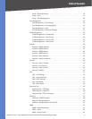
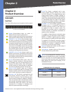
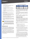
The Switch LEDs and ports are located on the front panel.
Front Panel of the SLM248G4PS
System (Green/Amber) Lights up green to
indicate that the Switch is powered on.
Lights up amber while the Switch is performing a
system self-test. Blinks amber if the self-test fails.
LINK/ACT (1-12, 25-36) (Green/Amber) Lights
up green to indicate a functional 10/100 Mbps
network link through the corresponding port with
an attached device that does not support Power
over Ethernet (PoE). Lights up amber to indicate
a functional 10/100 Mbps network link through
the corresponding port with an attached PoE
device. Blinks green while the Switch is actively
sending or receiving data over that port.
LINK/ACT (13-24, 37-48) (Green) Lights up to
indicate a functional 10/100 Mbps network link
through the corresponding port with an attached
device. Blinks while the Switch is actively sending
or receiving data over that port.
G1-G4 (Green/Amber) Blinks green when the
Switch is actively sending or receiving data at
10/100 Mbps over the corresponding port (G1
through G4). Blinks yellow when the Switch is
actively sending or receiving data at 1000 Gbps
over the corresponding port (G1 through G4).
Stack (G1-G4) (Amber) Lights up to indicate
that the corresponding port (G1 through G4) is
linked to another switch. (Two of these LEDs will
be lit if switch stacking is properly configured.)
Ethernet 1-48 The Switch is equipped with 48
auto-sensing, Ethernet network ports, which
use RJ-45 connectors. The Fast Ethernet ports
support network speeds of 10 Mbps or 100 Mbps.
They can operate in half- and full-duplex modes.
Auto-sensing technology enables each port to
automatically detect the speed of the device
connected to it (10 Mbps or 100 Mbps), and
adjust its speed and duplex accordingly.
G1-G4
The Switch is equipped with 4 auto-
sensing Gigabit Ethernet network ports, which
use RJ-45 connectors. The Gigabit Ethernet ports
support network speeds of 10 Mbps, 100 Mbps, or
1000 Mbps. They can operate in half- and full-duplex
modes. Auto-sensing technology enables each port
to automatically detect the speed of the device
connected to it (10 Mbps, 100 Mbps, or 1000 Mbps),
and adjust its speed and duplex accordingly.
miniGBIC (1-2) The miniGBIC (gigabit interface
converter) port is a connection point for a
miniGBIC expansion module, so the Switch can
be uplinked via fiber to another switch. The
MiniGBIC port provides a link to a high-speed
network segment or individual workstation at
speeds of up to 1000 Mbps.
To establish a Gigabit Ethernet connection using
a miniGBIC port, you will need to install a MGBT1,
MGBSX1, or MGBLH1 Gigabit expansion module
and use Category 5e cabling or fiber optic cabling.
To establish a Fast Ethernet connection using a
miniGBIC port, you will need to install a MFEFX1
(100BASE-FX) or MFELX1 (100BASE-LX) 100SFP
Transceiver and use fiber optic cabling.
Stack ID Displays the S
witch’s unit ID number if
the Switch is in stack mode.
Stack Master (Amber)
Lights up if the switch is
the stack Master during stack mode.
NOTE: On the SLM248G4PS, MiniGBIC ports are
shared with Gigabit Ethernet ports. If a miniGBIC
port is used, then the shared Gigabit Ethernet
port on the Switch cannot be used. The following
table defines the shared port mapping of the
SLM248G4PS Switch.
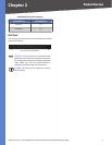
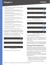
SLM248G4PS Shared Port Mapping
miniGBIC Port Gigabit Port
miniGBIC 1 Port G3
miniGBIC 2 Port G4