


24
Versatile Interface Processor (VIP6-80) Installation and Configuration Guide
OL-5078-01
Connecting Cables to the Port Adapter
Refer to the Installation and Configuration Guide that shipped with your specific port adapter for cabling
instructions.
Installing a VIP6-80
This section describes the procedure for installing a VIP6-80, or for inserting an interface filler.
Note To ensure compliance with EMI approvals by providing a tight EMI seal for the Cisco 7500 and the Cisco
7000 series routers, install interface processors first in the interface processor slots closest to the RSP
slots, and then work out to the interface processor slots furthest from the RSP slots. Refer to the “Product
Description” section on page 3 for more information on the interface processor slots on your router.
If you removed a VIP6-80 and do not intend to replace it with another VIP in its slot, follow this
procedure to insert an interface processor filler in the empty slot.
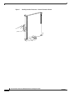
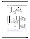
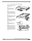
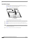
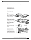
Figure 3 shows the functional details of inserting the VIP6-80 and using the ejector levers. Figure 2
shows proper handling of the VIP6-80 during installation.
Caution Remove or insert only one VIP6-80 at a time. Disrupting the sequence before the system has completed
verification can cause the system to detect spurious hardware failures.
Use the following procedure to install a new VIP6-80:
Step 1 Attach an ESD-preventive wrist strap between you and an unpainted chassis surface, if you have not
already done so.
Step 2 Ensure that a console terminal is connected to the console port (on the RSP or RSP7000) and that your
console is turned on, or that you have a reliable Telnet connection to the system.
Step 3 Hold the VIP6-80 handle with one hand and place your other hand under the carrier to support the
VIP6-80 and guide it into the slot. (See Figure 2.) Avoid touching the card or any connector pins.
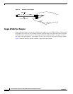
Caution To prevent ESD damage, handle interface processors by the handles and carrier edges only, similar to
that shown for port adapters in Figure 4.
Step 4 Place the back of the VIP6-80 in the slot and align the notch on the carrier with the groove in the slot.
(See Figure 3.)
Step 5 While keeping the VIP6-80 parallel to the backplane, carefully slide it into the slot until the back of the
faceplate makes contact with the ejector levers, and then stop. (See Figure 3b.)
Caution Use the ejector levers when installing or removing interface processors. An interface processor that is
partially seated in the backplane might cause the system to hang and subsequently crash, and shoving or
slamming the interface processor into the slot can damage the backplane pins and board.