CBM-253 User’s Manual
30
CITIZEN
6. DRAWER KICK-OUT CONNECTOR
(1) Drawer kick drive signal
The specified pulse will be output according to the specified pulse generating command (ESC <p>). When
using the parallel interface. it will be possible to determine the condition of the drawer opening and closing
switch from pin 34 of the interface connector. When using the serial interface. the switch condition may be
determined by utilizing the peripheral equipment status sending command (ESC <u>).
(2) Electrical characteristics
Driving voltage : DC 24V
Driving current : Maximum 1A (Should be less than 510 ms)
SW signal : Signal level 'L' = 0~0.5V
'H' = 3~5V
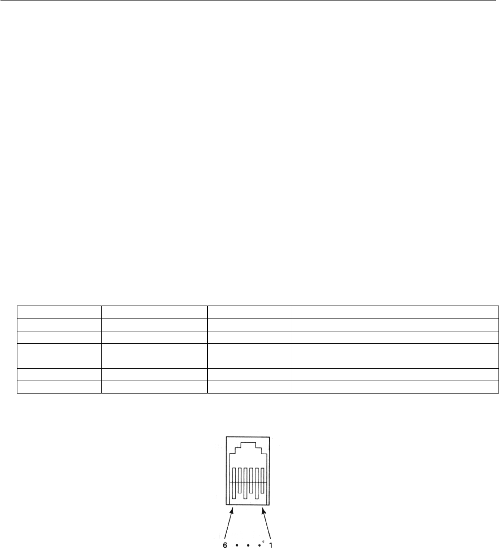
(3) Connector' s pin configuration
Connector pin Signal name Input/Output Function
1 FG – Frame ground
2 L1 Output Drawer l
3 SW Input Drawer opening and closing switch (* l)
4 Vp – Driving power source
5 L2 Output Drawer 2
6 GND – Signal ground
Used connector 285D-3660J- 100 (DDK)
Suitable connector 285D- 1660P-I06 (DDK) equivalent product
Note: It will not be possible to switch both drawer 1 and 2 to ON at the same time.
Note: Drawer operation will not be possible while the printer is printing.
Note: The duty should be kept to 20% or less.
Note: This connector is not to be used for connection to telephone lines.


