. . . . . . . . . . . . . . . . . . . . . . . . . . . . . .
3-4
Installing the Hub
Writer:
Chris Seiter
Project:
Installing the Hub
Comments:
299440-001
File Name:
2824_3.DOC
Last Saved On:
6/26/97 11:00 AM
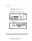
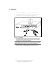
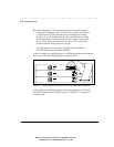
2. Remove the Smart Uplink port cover plate from the hub’s front panel.
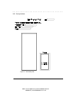
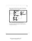
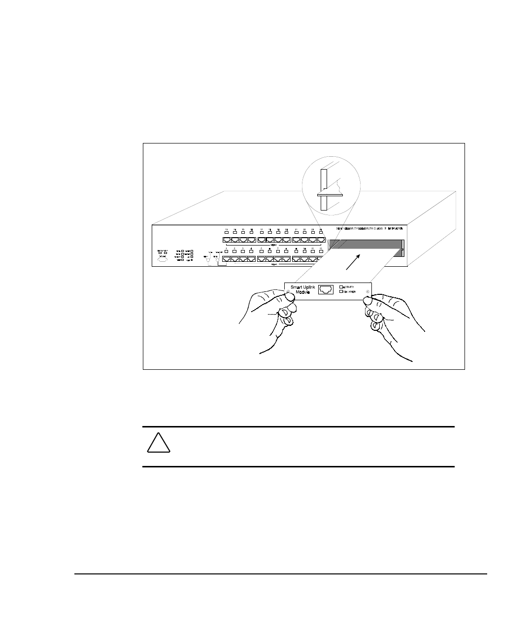
3. Insert the Smart Uplink module through the port hole, aligning the sides
of the SUM with the card guides inside the hub (Figure 3-4).
Figure 3- 4.
SUM Installation
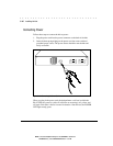
4. Carefully push the Smart Uplink module's 50-pin male connector into the
SUM socket on the hub motherboard until the SUM is firmly seated and
its faceplate is flush with the hub's front panel.
CAUTION:
Do not tighten the Smart Uplink Modules spring screws until
completing Step 4 of this procedure. If you tighten the spring screws before
the SUM is properly seated in the socket, you may damage the hub.
5. Secure the SUM to the hub by tightening the SUM's spring screws.


