


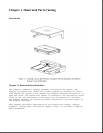
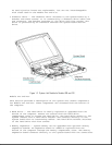
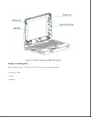
To replace the display assembly, the assembly must be removed from the
system unit module. This is done by removing the keyboard assembly,
disconnecting the display cable and display ground cable from the system
unit module, removing the tilt feet and handle brackets, removing the rear
clutch screws, and lifting off the display assembly.
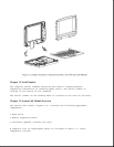
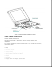
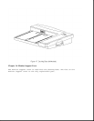
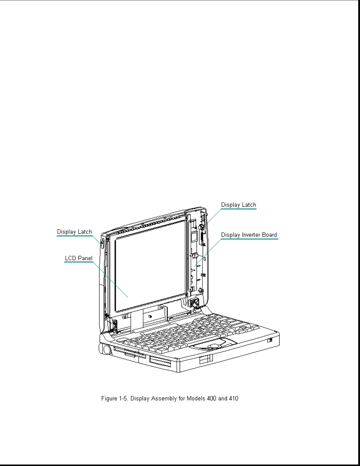
To service display components, do not remove the display assembly from the
system unit module (unless the display enclosure or clutch replacement is
required). Access display components (inverter board or latches) by
removing the bezel secured with four screws on the front of the display.
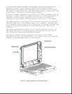
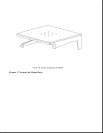
The display cable is a prefolded, flex cable that connects to the display
inverter board with a low insertion force (LIF) connector. The other end
of the display cable is exposed at the bottom of the display enclosure and
connects to the system board with a zero insertion force (ZIF) slide
connector.
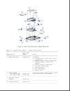
The display ground cable connects to the display shield on one end, and
the other end clips to a LIF-type spring clip located above the serial
port between the system board and system chassis.
The display inverter board is aligned to the right of the display
enclosure with pins. One end connects to the display cable; the other end
connects to the backlight cable of the LCD panel.