


Chapter 3. Removal and Replacement Procedures
Introduction
This chapter provides complete removal and replacement procedures for the
Compaq Contura 400 Family of Personal Computers. Procedures that apply to
specific models are indicated in parenthesis.
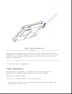
After completing removal and replacement procedures, run the diagnostics
program to verify that all components operate properly.
For replacement procedures, follow the removal procedures in reverse order
unless otherwise specified.
Chapter 3.1 Disassembly/Assembly Sequence Chart
This chart shows the order in which disassembly procedures are provided:
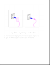
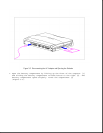
|-- 3.2 PREPARING THE COMPUTER
| |-- AC Adapter
| |-- Battery pack
|
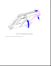
|-- 3.3 HANDLE BRACKET
|
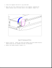
|-- 3.4 TILT FEET
|
|-- 3.5 HARD DRIVE
|
|-- 3.6 MEMORY EXPANSION BOARD
|
|-- 3.7 KEYBOARD ASSEMBLY
| |-- CPU cover
| |-- Keyboard
|
|-- 3.8 BATTERY COMPARTMENT COMPONENTS
| |-- Battery compartment
| |-- Anti-skid pad
| |-- Battery release spring and button
|
|-- 3.9 REAL-TIME CLOCK BATTERY (Models 400 and 410)
|
|-- 3.10 REAL-TIME CLOCK BATTERY (Models 420 and 430)
|
|-- 3.11 PROCESSOR UPGRADE OPTION (Model 400 Only)
|
|-- 3.12 INTEGRATED MECHANICAL TRACKBALL ASSEMBLY
| |-- (Model 400 and 410)
|
|-- 3.13 INTEGRATED OPTICAL TRACKBALL ASSEMBLY
|
|-- 3.14 DISKETTE DRIVE (All Models)
| |-- Diskette drive
| |-- Diskette drive bracket
|
|-- 3.15 THE SYSTEM BOARD (All Models)
|