


Fault Block Shielded Cable
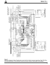
Table 3 shows the maximum distance between the con-
trol and the high-voltage switches for a range of conduc-
tor sizes and fault-block settings. The table is based on
conductor voltage drop and saturation of the current
sensing transformers in the switch. Lower actuating lev-
els and lower multipliers could allow longer lines.
However, the limitation on switch control cable lengths,
Table 2, preclude their use.
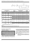
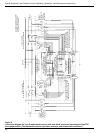
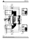
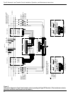
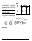
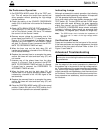
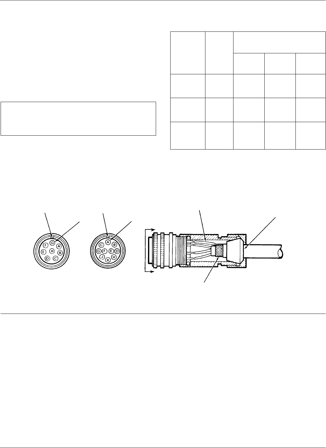
Shielded cable is required between the transfer switches
and the S control for operating the fault block accessory.
The shield must be grounded to the equipment housing
at both the switch and control ends. Shield connections
are made at connector plug pin or socket as shown in
Figure 13. This pin mates with the receptacle pin or sock-
et which is grounded in the switch and in the control as
shown in Figures 6 and 8.
Type S Automatic Load-Transfer Control Installation, Operation, and Maintenance Instructions
14
TABLE 3
Fault Block Cable Limitations
Max. Distance in Feet
Phase Between Switch and
Actuating Con- S Control
Current ductor
Level Size For X 8 For X 6 For X 4
(Amps) (AWG) Multi- Multi- Multi-
plier plier plier
640 18 600 1000 1800
640 16 950 1600 2900
640 14 1500 2550 4600
640 12 2400 4000 7300
448 18 1100 1700 –
448 16 1800 2700 –
448 14 2800 4300 –
448 12 4500 6850 –
320 18 1800 ––
320 16 2900 ––
320 14 4600 ––
320 12 7300 ––
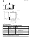
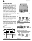
Figure 13.
Fault block cable plug.
KEYWAY
SOCKET A
SWITCH END
STRIP JACKET TO EXPOSE SHIELDING
RUBBER GROMMET
ACCOMMODATES
.50 TO .56 DIA. CABLE
A
A
KEYWAY
CONTROL END
PIN G
SOLDER #16 AWG JUMPER WIRE
FROM SHIELD TO PIN G TO
COMPLETE SHIELD CONNECTION
IMPORTANT: Only shielded cable is to be used on fault
block accessory and is mandatory to validate the
Cooper Power Systems warranty. Use of a non-shielded
cable could result in misoperation.