


5. Open SW1 and SW2 to simulate a backup clearing
the fault.
The PREFERRED TO ALTERNATE TIMER will start
and the preferred source high-voltage switch (HV1)
will open when the timer runs out, but the alternate
source high-voltage switch (HV2) will not close.
If alternate source switch (HV2) closes and the latch
relay (R1) contacts are not opening, check for open
contact between Accessory Tie Board tabs P and R
(Source I HV switch) and tabs S and T (Source II HV
switch).
6. Place OPERATION SELECTOR SWITCH (S3) to
manual, and operate MANUAL OPER SOURCE I
switch (S1) and MANUAL OPER SOURCE II switch
(S2) to CLOSE.
HV switch (HV1 or HV2) will not close.
If either switch closes and the latch relay (R1) con-
tacts are not opening, check for open contact
between Accessory Tie Board tabs P and R (Source
I HV switch) and tabs S and T (Source II HV switch).
7. Close test switch SW2 to restore preferred source
voltage to the control. After the ALTERNATE TO
PREFERRED TIMER runs out, reset the fault block
accessory per instructions on the front panel.
The FAULT BLOCK OPERATED light will go out and
the preferred source high-voltage switch will close.
If the FAULT BLOCK OPERATED light does not go
out, the problem is most likely in the TRIP RESET
BOARD.
Follow steps 8 through 11 to conduct a complete check
involving all the phases of both high-voltage switches.
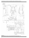
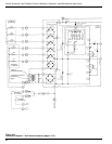
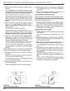
8. Connect the phases in series as shown in Figure 24
and retest.
Because of the series hook-up, pickup should occur
at 1/2 the actuating current setting.
If pickup current is other than 1/2 of setting, the polar-
ity of a CT could be reversed.
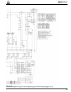
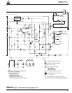
9. Connect another two phases in series as shown in
Figure 25 and retest.
Results should be the same as in preceding step 8.
10. Repeat step 8 and 9 for the other high-voltage switch
to complete checking all six CTs, their connections
and polarity.
11. Remove the shorting jumper from the ground fault
resistor upon completion of phase testing.
Ground Minimum Actuating Current
When checking the ground minimum actuating current,
the phase fault sensing portion of the accessory circuit
must be disabled to prevent the possibility of erroneous
test results. Proceed as follows:
1. Disable the phase sensing circuit by placing a short-
ing jumper from the BLOCK tab on the phase resistor
card to tab L on the accessory tie-board (Figure 26).
2. Repeat steps 2 through 7 of the Phase Minimum
Actuating Current test procedure.
Automatic Reset of Fault Block
1. Close test switches SW2 and SW3 to supply voltage
to the control.
The preferred source high-voltage switch (HV1) will
close.
2. Close SW1 and raise the test current until the FAULT
BLOCK OPERATED lamp lights indicating that fault
block has been activated.
3. Open SW2 to simulate the back-up device opening
and simultaneously open SW1 to clear the fault.
The PREFERRED TO ALTERNATE TIMER will start
to run.
4. Close SW2 to simulate reclosing of Source 1 back-
up device. Quickly close SW1 and raise the test cur-
rent to greater than 5 Amps but less than ground
actuating level.
The FAULT BLOCK OPERATED lamp will go out in
about 10-15 seconds indicating the accessory has
reset.
If FAULT BLOCK OPERATED lamp does not go out,
the trouble is most likely in the Trip-Reset board
(assuming the previous tests had passed).
Type S Automatic Load-Transfer Control Installation, Operation, and Maintenance Instructions
34
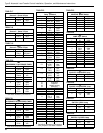
Figure 24.
Test Connections for Step 8.
A
JUMPER
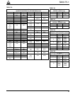
Figure 25.
Test Connections for Step 9.
A
JUMPER