


Type S Automatic Load-Transfer Control Installation, Operation, and Maintenance Instructions
30
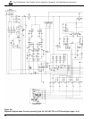
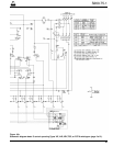
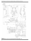
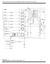
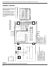
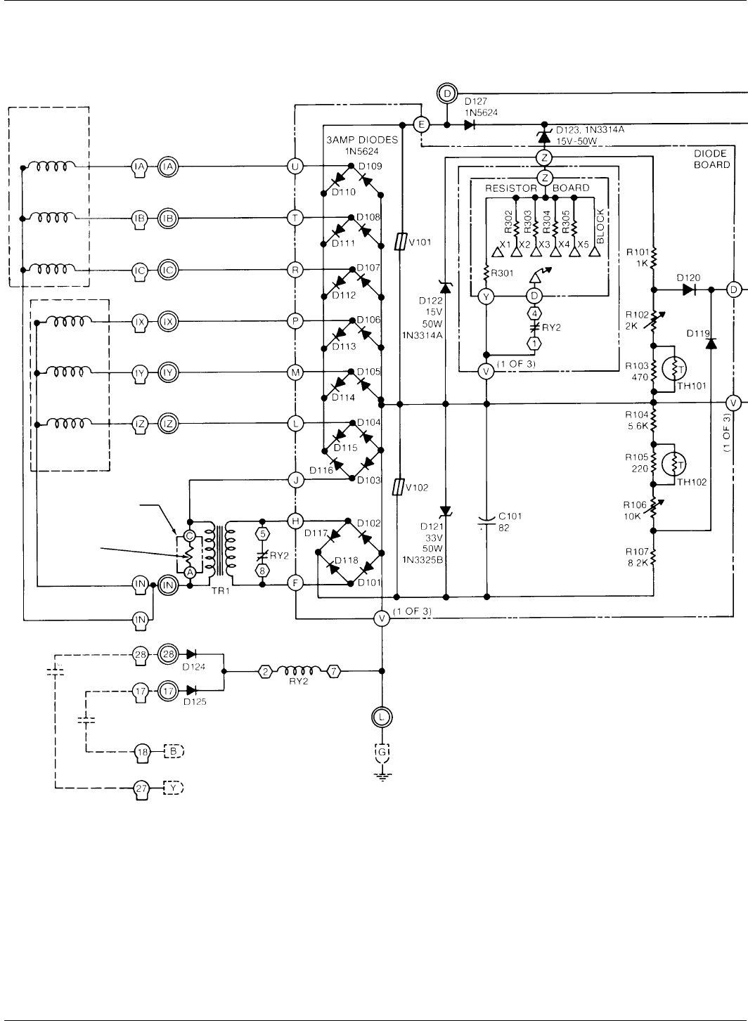
Figure 21a.
Schematic diagram – fault block accessory (page 1 of 2).
SOURCE I
H.V. SWITCH
SOURCE II
H.V. SWITCH
A
Ø
BØ
CØ
AØ
BØ
CØ
PART OF
RESISTOR BOARD
GROUND ACTUATING
RESISTOR
R306
SOURCE II
H.V. SWITCH
a
2
a1
SOURCE I
H.V. SWITCH
+