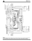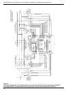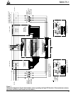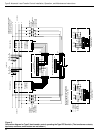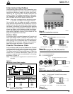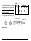
A typical automatic transfer scheme is illustrated in Figure 2.
Initial Programming
The control must be programmed with all necessary
operating settings prior to operation with energized
switchgear. For the desired settings refer to the
Operating Instructions section in this manual.
Mounting the Control
Mount the S control in a convenient, accessible location.
Maximum distances between the high-voltage transfer
switches and potential sensing transformers and the con-
trol depends upon the size of the control cable wire and
the length of various cable combinations. (See the
Interconnecting Cables section in this manual.) Keep in
mind that the longer the cable lengths, the greater the
susceptibility to surge damage. Therefore, for optimum
reliability and economy, locate the switches and trans-
formers as near as possible to the control.
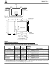
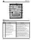
Mounting dimensions are provided in Figure 3.
• For pole-mounted installation, a hole and keyway in
the control mounting bracket accommodates a 5/8”
bolt.
• For substation installation, the control is factory
installed. Leveling is not required.
Grounding the Control
The control cabinet must be grounded. A grounding con-
nector on the underside of the cabinet will accommodate
No. 14 solid through No. 4 stranded conductors.
For efffective surge protection all control and power con-
ductors for the S control must be routed parallel to a cor-
responding ground path. For example, the AC power
supply for the control should be parallel to and equal in
length to the transformer ground path. The control cable
should be parallel to and routed close to the switchgear
ground path.
Before Placing the Control and
Switchgear into Service
Prior to placing the control and switchgear into service,
the following installation procedures must be properly
completed and verified:
1. Control properly mounted for the installation.
2. Equipment installed according to all locally approved
standards and practices.
3. Control and switchgear properly grounded in accor-
dance with guidelines in this manual.
4. AC power connected to the control.
5. All control programming entered and verified by
appropriate personnel.
Equipment Required
The following equipment is required for a load-transfer
installation:
Type S Load-Transfer Control
The control, with or without the fault block accessory, is
housed in a cabinet whose outline and mounting dimen-
sions are shown in Figure 3. The control cabinet can be
mounted on a pole or substation structure. Leveling is not
required. Both the cabinet door and the hinged front
panel are equipped with hold-open latches to prevent
them from swinging in the open position.
Motor Operated Switches
The three-phase, load break switches require a special
wiring accessory for operation with the Type S control. In
addition, if fault block is provided, the switches must be
equipped with 1000:1 ratio current transformers also
available as a factory-installed switch accessory. See the
switch installation manual for overall and mounting
dimensions and for wiring diagrams.
Potential Transformers
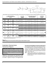
Three-phase voltage sensing is required for control oper-
ation. Transformer connections and voltages for various
distribution system connections are shown in Figure 5.
The voltage sensing relays of the Type S control drop out
on a decreasing voltage at 75 volts (min) and pick up on
an increasing voltage at 97 volts (max). The control
requires 120 Vac, 60 Hz, 500 VA (min) to operate the
transformer switches. Quiescent power dissipation at
120 Vac is 18 watts.
Type S Automatic Load-Transfer Control Installation, Operation, and Maintenance Instructions
6
INSTALLATION INSTRUCTIONS
WARNING: Hazardous voltage. Solidly ground
all equipment. Failure to comply can result in
death, severe personal injury, and equipment damage.
T223.2
!
CAUTION: Equipment misoperation. Do not
energize this equipment until all control settings
have been properly programmed and verified. Refer to
the Control Programming and Operation section of this
manual for programming procedures. Failure to com-
ply can result in misoperation (unintended operation),
equipment damage, and personal injury. G118.1
!


