


Manual Control Functions
Abnormal output readings at TB1 indicate a malfunctioning
control. This procedure describes the terminal functions
under manual direction and suggests areas for investigation.
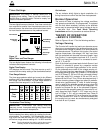
1. Terminals 11 and 21 provide the power to charge the
springs in the switch actuator and are constantly
energized. If terminals 11 and 21 are not energized,
the transfer bus is not energized.
A. Make sure that either phase B of the preferred
source or phase Y of the alternate source is ener-
gized. These phases supply the transfer bus.
Measure beyond the fuses.
B. Relays R7 and R11 control power to the transfer
bus. Relay R7 picks up when phase Y is ener-
gized; Relay R11 picks up if phase B is energized
and phase Y is deenergized.
2. Terminals 15 and 25 provide 120 Vac closing power
(15 closes Source I switch, and 25 closes Source II
switch). Terminals 13 and 23 provide 120 Vac open-
ing power (13 opens Source I switch and 23 opens
Source II switch).
A. Terminals 13, 23, 15 and 25 are energized from
the transfer bus through the MANUAL OPER.
switches, S1 and S2.
(1) If the control is equipped with the fault block
accessory, normally closed contacts of the fault
block relay (RY1) are connected between tabs
FP and FR of the relay tie board to complete the
circuit to terminal 15 and between tabs FS and
FT to complete the circuit to terminal 25.
(2) If the control does not use the fault block
accessory, jumpers are provided between tabs
FP and FR and FS and FT of the relay tie board
to complete the closing power circuits to the
transfer switches.
3. Terminals 14 and 24 are grounded by an “a” contact
(N.O.) in the H.V. transfer switches to energize relays
R4 and R5 respectively during the “opening” half of a
parallel return transfer.
4. Terminals 16 and 26 are energized (120
Vac) on the “closing” half of a non-parallel
return transfer. They are energized from a
“b” contact (N.C.) in the H.V. transfer switch-
es; 16 is energized from Source I high- volt-
age switch and 26 is energized from Source
II high-voltage switch.
Automatic Control Functions
The control may operate properly by manual direction but
malfunction in its automatic mode. The automatic section
responds to the positions of R2 and R6 in conjunction
with the selected operating mode as set on S4, the
SOURCE PREFERENCE and RETURN MODE switch.
Its output is the single-coil latching relay, R1.
1. R2 is energized from phase A of Source I through
N.O. contacts of R9 in phase B and R10 in phase C.
The action of R2 can be observed through its trans-
parent cover and can be checked electrically across
tabs 31 and 32 on the relay tie board which connect to
a N.C. contact of the relay.
2. R6 is similarly energized from phase X of Source II
through R7 in phase Y, and R8 in phase Z. Tabs 41
and 42 connect to a N.C. contact of R6.
3. Operation of the appropriate time delay relay can be
checked by verifying that the LED timer is illuminated.
4. The single-coil latching relay (R1) is electrically oper-
ated and magnetically held. It is latched directly from
the 120 Vac transfer bus through diode DL in the auto-
matic mode or diode DL1 in the manual mode. It is
reset through the 15 K ohm resistor and either diodes
DR or DR1.
5. With the control in an automatic mode of operation,
the position of the latching relay can be determined at
the Latching Relay Test jacks (T1, T2, T3) on the front
panel of the control.
A. When 120 Vac is present between T1 and T3, the
relay is in the “latched” position and the control
seeks to connect the load to Source I.
B. When 120 Vac is present between T2 and T3, the
relay is in the “reset” position and the control seeks
to connect the load to Source II.
C. If the latching relay assumes the expected position
after the proper time delay, the automatic section
of the control is functioning properly.
S260-75-1
23
!
SAFETY
FOR LIFE
!
SAFETY
FOR LIFE
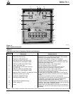
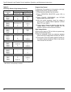
TABLE 6
Voltage Readings on TB1
Voltage to Ground
MANUAL OPER. MANUAL OPER.
Term SOURCE I SOURCE II
on Switch (S1) Switch (S2)
TB1 Quiescent Close Open Close Open
11 120 Vac 120 Vac 120 Vac 120 Vac 120 Vac
15 170 Vdc* 120 Vac 170 Vdc* 170 Vdc* 170 Vdc*
14 170 Vdc* 170 Vdc* 170 Vdc* 170 Vdc* 170 Vdc*
13 0 0 120 Vac 0 0
160 0000
260 0000
23 0 0 0 0 120 Vac
24 170 Vdc* 170 Vdc* 170 Vdc* 170 Vdc* 170 Vdc*
25 170 Vdc* 170 Vdc* 170 Vdc* 120 Vac 170 Vdc*
21 120 Vac 120 Vac 120 Vac 120 Vac 120 Vac
* Rectified 120 Vac impressed on capacitor. Drops to 0 if LAMP TEST
switch (S6) is depressed.