Inrush Restraint
The inrush-restraint feature prevents inrush currents
above the minimum actuating level from actuating the
accessory. This is accomplished by raising the phase
actuating level by some multiple for a predetermined time
after service is restored. Ground actuating level detection
is blocked for the duration of the raised phase actuating
level. Proceed as follows:
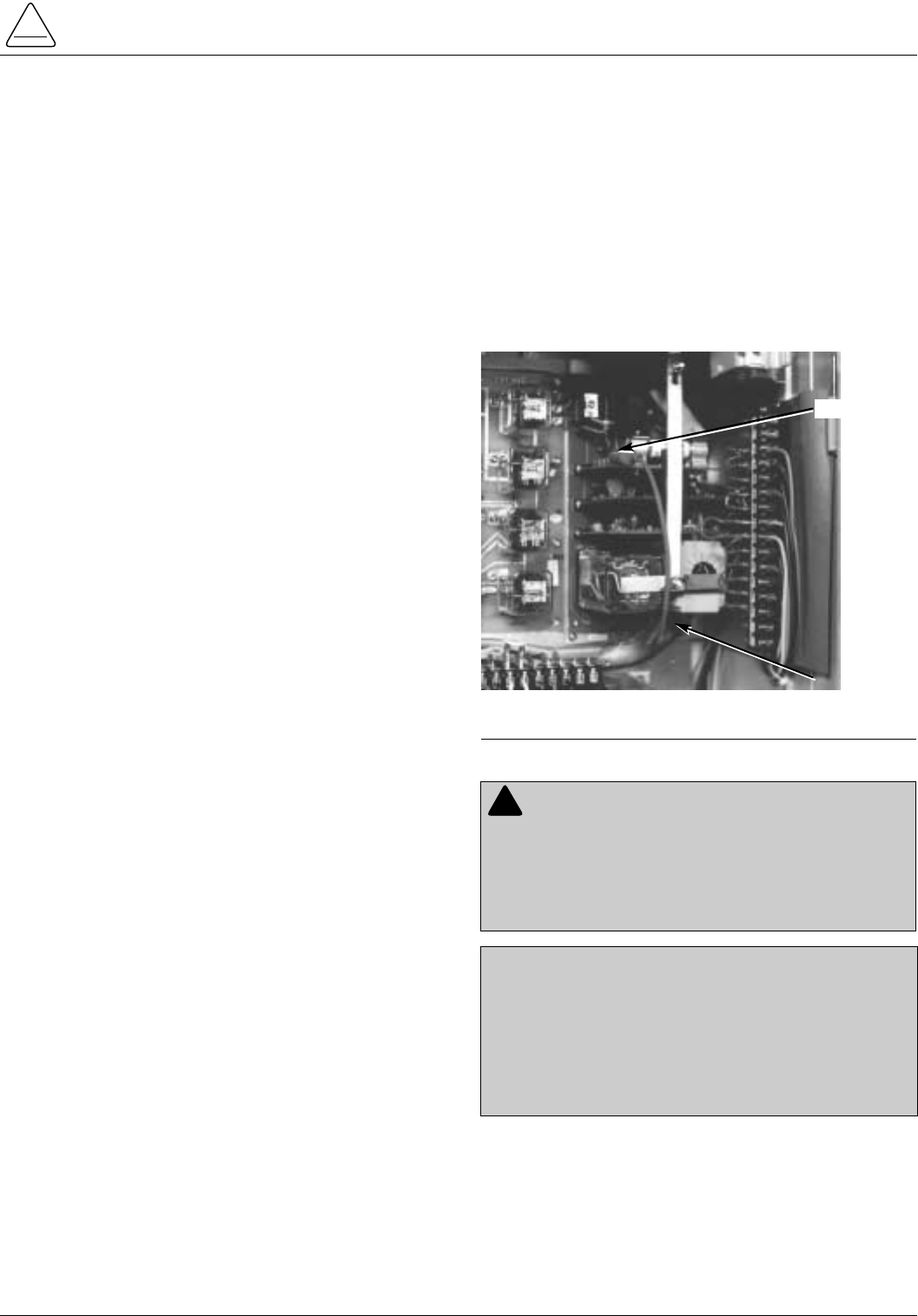
1. Disable the ground sensing circuit by shorting the
ground fault resistor (Figure 26).
2. Set the inrush-restraining multiplier on the phase actu-
ating card and the raised fault-level duration on the
timer to the values at which they are to be checked.
3. With the preferred source high-voltage switch (HV1)
closed, close test switch SW1 and raise the equiva-
lent test current to a value above the maximum actu-
ating level for the setting, but below the multiplied set-
ting. (See Table 7 for maximum current test values.)
4. Without disturbing this current setting, open SW1.
5. Close test circuit switches SW2 and SW3 to apply
voltage to the control.
6. Momentarily close and open SW1 before the raised
duration timer runs out, to simulate an inrush current.
The FAULT BLOCK OPERATED lamp will not light.
If the FAULT BLOCK OPERATED lamp does light,
proceed as follows:
A. Recheck current calculations. (Test current should
exceed actuation level but be less than inrush level.)
B. Check if momentary faults were applied before
timer elapsed.
C. Check if timing relay picked up after either HV1 or
HV2 was closed. Check presence or absence of 120
Vac at Accessory Tie Board terminal 17 when HV1
operates and terminal 28 when HV2 operates.
D. Check for trouble in delay relay contacts or resis-
tor board.
7. Close SW1 and leave closed to simulate a perma-
nent fault on the load side.
The FAULT BLOCK OPERATED lamp will light after
the raised duration timer runs out.
If FAULT BLOCK OPERATED lamp does not light,
the problems are similar to step 6 above.
8. Open switches SW2 and SW3 to remove voltage
from the accessory.
9. Raise the test current to a value just above the raised
multiple value.
10. Without disturbing this current setting, open SW1.
11. Again close switches SW2 and SW3 to apply voltage
to the control.
12. Close SW1 to simulate a high-level fault on the load
side of the switch.
The FAULT BLOCK OPERATED lamp will light imme-
diately indicating the fault is greater than the inrush
current restraining setting.
If FAULT BLOCK OPERATED lamp does not light
immediately, then
A. Recalculate expected current.
B. Verify that jumper on resistor board is on correct
tab.
If FAULT BLOCK OPERATED lamp still does not
light immediately, the resistor board may be defec-
tive. Contact your Cooper Power Systems represen-
tative.
13. Remove the shorting jumper from the ground fault
actuating cartridge upon completion of the test.
Return the Control to Service
1. The control must be programmed with all the neces-
sary operating settings and verified by the appropri-
ate personnel prior to operation with energized
switchgear.
2. Verify status of high voltage switches according to
system requirements.
3. Reconnect cables and ground the control.
4. Apply Source I and Source II voltage to the control.
S260-75-1
35