


Testing Fault Block Operation
The operation of the fault block accessory can be
checked by backfeeding a 500:5 (or other available ratio)
current transformer, located in the primary loop of one
phase of the preferred source high-voltage switch, from a
variable 120 Vac source. The 500:5 ratio provides approx-
imately 1 Amp of output test current for every 10 mA of
input current. However, to eliminate error due to CT satu-
ration, a separate metering CT and meter should be used
to read the actual test current.
Test Circuit and Equipment
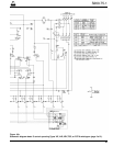
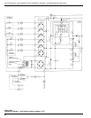
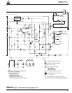
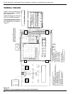
A suggested test setup is shown in Figure 22. If the con-
trol is equipped with the plug and receptacle accessory,
use the existing cables to interconnect the motor opera-
tors of both high-voltage switches and the CT sensing
circuits of the preferred source switch to the S control. If
plugs and receptacles are not provided, wire the switch-
es directly to the appropriate terminal blocks as shown in
Figures 6 or 8.
Test Procedure and Troubleshooting
Phase Minimum Actuating Current
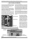
1. Disable the ground sensing circuit by shorting the
ground fault resistor (Figure 22).
2. Set the inrush current multiplier at X1.
3. Close test circuit switches SW2 and SW3 to apply
voltage to the control.
The preferred source high-voltage switch (HV1) will
close.
4. Close test switch SW1 and slowly raise the test current
until the FAULT BLOCK OPERATED light goes on.
The test current should be within the limits specified in
Table 7.
If FAULT BLOCK OPERATED light fails to come
on at the expected level, proceed as follows:
A. Check lamp with LAMP TEST switch (S6).
B. Recheck calculations for proper meter reading.
C. Is ground resistor cleanly shorted out?
D. Did latch relay R1 transfer position?—lamp is only
an outward indication of relay position.
E. Are all cable connections secure?
F. Voltage from Accessory Tie Board, Tab D to
Ground, Tab L, should be approximately 15 Vdc,
average, at actuating level. If observed voltage is
approximately 6 volts too low, trouble is probably in
the Trip Reset Board; if voltage is too high, trouble
is probably in either Diode or Resistor Boards.
G. AC rms voltage from “IN” to “IA” (or whatever
phase is energized) should be about 17 V at actu-
ating level. If correct voltage is observed, the CT
input is correct.
S260-75-1
33
!
SAFETY
FOR LIFE
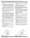
Figure 23.
Disabling ground sensing circuit.
020082KM
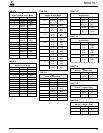
Actuating Actuating Current Limits
Current (Amps)
Setting
(Amps) Minimum Maximum
10 9 11
14 12.6 15.4
20 18 22
28 25.2 50.8
40 36 44
56 50.4 61.6
80 72 88
112 101 123
160 144 176
274 247 301
320 250 352
448 403 493
TABLE 7
Test Current Values for Fault Block Accessory
WARNING: Hazardous voltage caused by back-
feeding transformers. Isolate potential transform-
ers from source bushings using potential transformer
dead-break disconnect switches located on the
source-side panel. Failure to do so will result in risk of
possible contact with high voltage at the source bush-
ings, which may cause death or severe personal injury.
T273.0
!
IMPORTANT: When checking the phase minimum
actuating current the ground fault sensing portion of
the accessory must be disabled. Testing on an individ-
ual phase basis without disabling ground fault sensing
will cause the accessory to activate at the ground fault
level.