


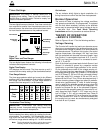

Output of the Control
To determine if the problem is in the control or the high-
voltage transfer switch, proceed as follows:
1. Disconnect the switches from the control.
2. Place OPERATION SELECTOR switch (S3) to
MANUAL.
3. Place SOURCE PREFERENCE and RETURN
MODE switch (S4) to NO PREF.
4. With the control energized, check the voltage to
ground at the “Transfer Switch Operators” terminal
board, TB1, per Table 6.
5. If these output voltages are obtained, check the high-
voltage switch. If the output voltages are not
obtained, check the manual control functions.
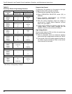
High-Voltage Switch
Normal control output at TB1 but failure to operate sug-
gests a malfunctioning switch.
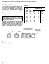
1. With an ohmmeter, check the resistance between
points of the high-voltage switch actuator per Table 5.
2. If the control circuit of the switch operator checks out,
the trouble may be mechanical. Refer to the mainte-
nance manual for the switch.
Type S Automatic Load-Transfer Control Installation, Operation, and Maintenance Instructions
22
Switch Ohmmeter Reading
Receptacle
Pin Switch Open Switch Closed
Type VR, VLR, VRV — Standard Operator
B to C Motor ∞
B to D ∞ Trip Coil
B to E ∞ 0
D to F 0 0
Type VR, VLR, VRV — Quick Close Operator
A to D * ∞
B to C Quick Close Coil ∞
B to D ∞ Trip Coil
B to E ∞ 0
D to F 0 0
Type TSC
B to C Motor ∞
B to F ∞ Motor
B to E ∞ 0
D to F 0 ∞
Type PST-6 with C Interrupter #1
E to R Close Coil ∞
M to N ∞ 0
P to E * ∞
S to V 0 ∞
T to U ∞ Trip Coil
Type PST-6 with C Interrupter #2
B to C ∞ 0
D to E * ∞
E to F Close Coil ∞
G to K 0 ∞
H to J ∞ Trip Coil
Type PST-9 with C Interrupter #1
E to F ∞
A to C ∞
C to E ∞
B to C ∞
C to D ∞
Type PST-9 with C Interrupter #2
L to M ∞ 0
G to J 0 ∞
J to L ∞ Trip Coil
H to J * ∞
J to K Close Coil ∞
TABLE 5
Continuity Check of High-Voltage Switches
* Will read motor resistance if closing spring is not charged, will
read infinity if closing spring is charged.