


System Outline
Service Manual
4-13
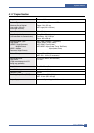
Charge Voltage (MHV)
Input Voltage : 24 V DC 15%
Output Voltage : -1.2KV ~ -1.8KV DC 3%
Output Voltage Rising Time : 50 ms Max
Output Voltage Falling Time : 50 ms Max
Output Control Signal(MHV-PWM) : CPU is HV output when PWM is Low
Cleaning Voltage (THV-)
The (+) Transfer Voltage is not outputted because the THV PWM is controlled with high.
The (-) Transfer Voltage is outputted because the THV-Enable Signal is controlled with low
The output fluctuation range is big because there is no Feedback control.
Developing Voltage (DEV)
Input Voltage : 24 V DC 15%
Output Voltage: -200V ~ -600V DC 3%
Output Voltage Fluctuation Method : PWM Control
Line Regulation : under 3% (fluctuation input 21.6V ~ 27.6V)
Load Regulation : Under 3%
Output Voltage Rising Time : 50 ms Max
Output Voltage Falling Time : 50 ms Max
Output Control Signal (BIAS-PWM) : the CPU output is HV output when PWM is low .
Supply
Output Voltage : -300V ~ -800V DC 5% (ZENER using, DEV )
Line Regulation : under 3% (fluctuation input 21.6V ~ 27.6V)
Load Regulation : Under 3%
Output Voltage Rising Time : 50 ms Max
Output Voltage Falling Time : 50 ms Max
Output Control Signal (BIAS-PWM) : the CPU is HV output when PWM is low .