


96 Installing System Components
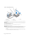
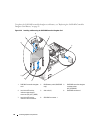
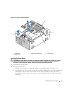
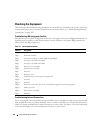
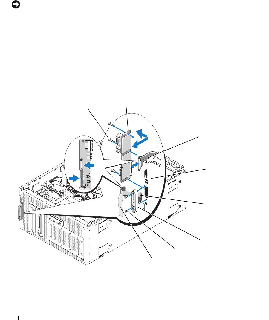
7 Disconnect the control panel cable from the back of the control panel. See
Figure 3-27
.
NOTICE: Do not pull on the cable to unseat the connector. Doing so can damage the cable.
a
Squeeze the metal tabs on the ends of the cable connector.
b
Gently work the connector out of the socket.
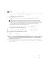
8
Remove the display module:
a Insert the end of a paper clip into the hole on the right side of the display module and gently
pry the label off.
b Using a T10 Torx driver, remove the two screws that secure the display module to the system
chassis.
c Remove the display module from the chassis cutout.
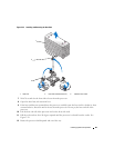
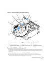
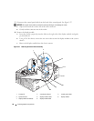
Figure 3-27. Removing the Control Panel Assembly
1 screws (3) 2 control panel board 3 control panel cable
4 system chassis 5 display module cable 6 display module
7 display module screws (2) 8 display module label
6
5
4
2
3
7
8
1