


1. If you only have one memory module, install it in the connector labeled "JDIM1" on the system board. Install a second memory module in the connector
labeled "JDIM2."
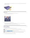
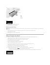
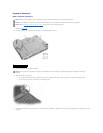
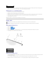
2. Align the notch in the memory module with the slot in the center of the socket.
3. Slide the edge connector of the module firmly into the socket at a 45- degree angle, and rotate the module down until you hear a click. If you do not
hear the click, remove the module and reinstall it.
4. Replace the cover and tighten the two captive screws.
Mini PCI Card Assembly
You must remove the Mini PCI card before the system board can be removed.
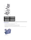
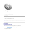
Removing the Mini PCI Card
1. Remove the memory module cover.
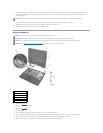
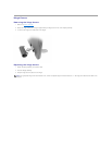
2. Disconnect the Mini PCI card from the antenna cables.
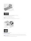
3. To release a Mini PCI card from its socket, spread apart the metal securing tabs until the card pops up slightly.
4. Lift the Mini PCI card out of its connector.
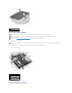
Replacing the Mini PCI Card
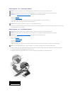
1. Align the Mini PCI card with the socket at a 45-degree angle, and press the Mini PCI card into the socket.
2. Lower the Mini PCI card toward the inner tabs to approximately a
20-degree angle.
3. Continue lowering the Mini PCI card until it snaps into the inner tabs of the socket.
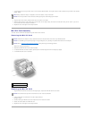
4. Attach the antenna cables to the Mini PCI card.
5. Replace the cover and tighten the two captive screws.
HINT: Memory modules are keyed, or designed to fit into their sockets, in only one direction.
NOTICE: The memory module must be inserted at a 45-degree angle to avoid damaging the connector.
NOTICE: Disconnect the computer and any attached devices from electrical outlets, and remove any installed batteries.
NOTICE: To avoid ESD, ground yourself by using a wrist grounding strap or by touching an unpainted metal surface on the computer.
NOTICE: Read "Preparing to Work Inside the Computer" before performing the following procedure.
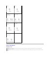
1
antenna connectors on card (2)
2
antenna cables (2)
NOTICE: The connectors are keyed for correct insertion; do not force the connections.