


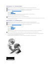
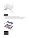
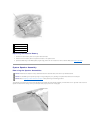
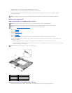


1. Align the pin-1 corner of the microprocessor module with the pin-1 corner of the ZIF socket, and insert the microprocessor module.
When the microprocessor module is correctly seated, all four corners are aligned at the same height. If one or more corners of the module are higher
than the others, the module is not seated correctly.
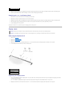
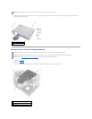
2. Tighten the ZIF socket by turning the cam screw clockwise to secure the microprocessor module to the system board.
3. Update the BIOS using a flash BIOS update program floppy disk or CD. For instructions on how to flash the BIOS, see "Flashing the BIOS."
Flashing the BIOS
To update the BIOS:
1. Make sure that the AC adapter is plugged in and that the main battery is installed properly.
2. Turn on the computer. The following error message appears:
System hardware failures: #0010
Strike the F1 key to shutdown
3. Instead of pressing , insert the flash BIOS update floppy disk or
CD into the appropriate drive and press , and then press . The computer displays the following message on the screen:
Failure override
Processor update failure. Reload current BIOS
Strike the F1 key to continue, F2 to run the setup utility.
4. Press . The computer continues to boot and updates the new BIOS.
5. Press to enter the system setup program and reset the boot sequence with the appropriate drive, if required.
6. Press to exit the system setup program.
7. Remove the flash BIOS update floppy disk or CD from the drive and restart the computer.
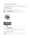
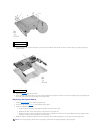
Reserve Battery
Removing the Reserve Battery
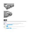
1. Remove the hard drive.
2. Remove the keyboard.
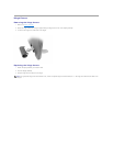
3. Disconnect the reserve battery cable from the system board connector.
4. Pry the reserve battery free from the system board. The reserve battery is attached to the system board with a piece of adhesive tape.
5. Remove any remnants of the adhesive tape from the system board.
HINT: The pin-1 corner of the microprocessor module has a triangle that aligns with the triangle on the pin-1 corner of the ZIF socket.
NOTICE: You must position the microprocessor module correctly in the ZIF socket to avoid permanent damage to the module and the socket.
NOTICE: Hold the microprocessor down while turning the cam screw to prevent intermittent contact between the cam screw and microprocessor (see
"Removing the Microprocessor Module").
NOTICE: The reserve battery provides power to the computer's RTC and NVRAM when the computer is turned off. Removing the battery causes the
computer to lose the date and time information as well as all user-specified parameters in the BIOS. If possible, make a copy of this information before
you remove the reserve battery.
NOTICE: Disconnect the computer and any attached devices from electrical outlets, and remove any installed batteries.
NOTICE: To avoid ESD, ground yourself by using a wrist grounding strap or by touching an unpainted metal surface on the computer.
NOTICE: Read "Preparing to Work Inside the Computer" before performing the following procedure.