


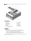

NOTE: The front and back wheel plates are labeled.
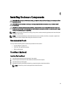
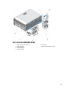
1. To reduce the chassis weight, remove the following (if required):
a) Front bezel (if installed)
b) Hard drives. See Removing A Hot-Swap Hard Drive.
c) Server modules. See Removing A Server Module.
d) Power supplies. See Removing A Power Supply.
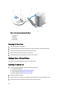
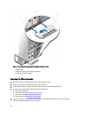
2. Rotate the system feet inward and lay the enclosure on its side on a sturdy, stable surface with the cover release
latch side on top, and the base of the enclosure extending slightly off the surface edge.
3. Tilting the front wheel plate towards the hooks on the system base cover, align the metal stand on the wheel plate
with the hooks.
4. Insert the metal stand on the front wheel plate into the hooks until firmly seated.
5. Lower the other end of the front wheel plate to the chassis base and align the slot on the wheel plate with the tab
on the system base cover.
6. Tighten the screw on the front wheel plate to secure it to the system base cover.
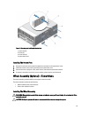
7. Tilting the back wheel plate towards the hooks on the system base cover, align the metal stand on the wheel plate
with the hooks.
8. Insert the metal stand on the back wheel plate into the hooks until firmly seated.
9. Lower the other end of the back wheel plate to the chassis base and align the slot on the wheel plate with the tab
on the system base cover.
10. Tighten the screw on the back wheel plate to secure it to the system base cover.
11. Place the enclosure upright on a sturdy, stable surface.
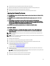
12. If removed, reinstall the hard drives, server modules, power supplies, and front bezel.
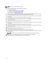
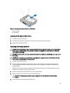
13. Align the tabs on the power cable retention bracket with the slots on the back end of the chassis base, below the
power supply bay.
NOTE: Place the enclosure in the upright position before installing the power cable retention bracket.
14. Insert the power cable retention bracket into the slots and slide the bracket to the left to lock it.
15. Route the power supply cables through the power cable retention bracket.
36