


9. If removed, reinstall the hard drives, server modules, and power supplies.
10. Reconnect the enclosure to its electrical outlet and turn the enclosure on, including any attached peripherals.
11. Turn on the server modules using the operating system commands or the CMC.
12. If applicable, install the front bezel.
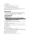
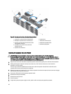
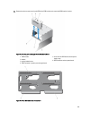
Hard-Drive Backplane
Depending on your system configuration:
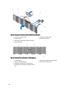
25–Hard Drive
System Supports
2.5 inch SAS or SAS-SSD backplane
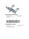
12–Hard Drive
System Supports
3.5 inch SAS or SAS-SSD backplane
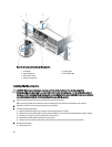
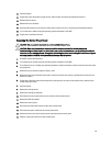
Removing The Hard-Drive Backplane
CAUTION: Many repairs may only be done by a certified service technician. You should only perform
troubleshooting and simple repairs as authorized in your product documentation, or as directed by the online or
telephone service and support team. Damage due to servicing that is not authorized by Dell is not covered by your
warranty. Read and follow the safety instructions that came with the product.
1. If installed, remove the front bezel.
2. Turn off the server modules using the operating system commands or the CMC.
3. Turn off the enclosure, including any attached peripherals, and disconnect the enclosure from the electrical outlet.
4. To reduce the chassis weight, remove the following (if required):
a) hard drives
b) server modules
c) power supplies
5. If applicable, rotate the system feet inward and lay the system on its side on a flat stable surface, with the cover
release latch side on top.
6. Open the system.
CAUTION: To prevent damage to the hard drives and hard-drive backplane, you must remove the hard drives
from the enclosure before removing the hard-drive backplane.
CAUTION: You must note the number of each hard drive and temporarily label them before removal so that
you can replace them in the same locations.
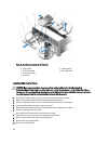
7. Remove all hard drives.
8. Remove the cooling shroud.
9. Remove the cooling-fan assembly.
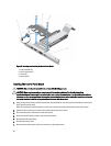
10. Remove the backplane expander board.
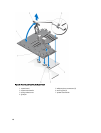
11. Disconnect the power cables from the backplane.
12. If applicable, disconnect the power/data cable from the optical drive.
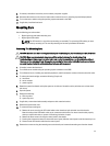
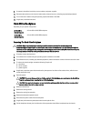
13. Pull the backplane release pins in the direction of the system board and lift the backplane from the chassis.
99