


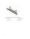
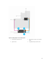
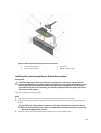
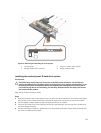
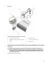
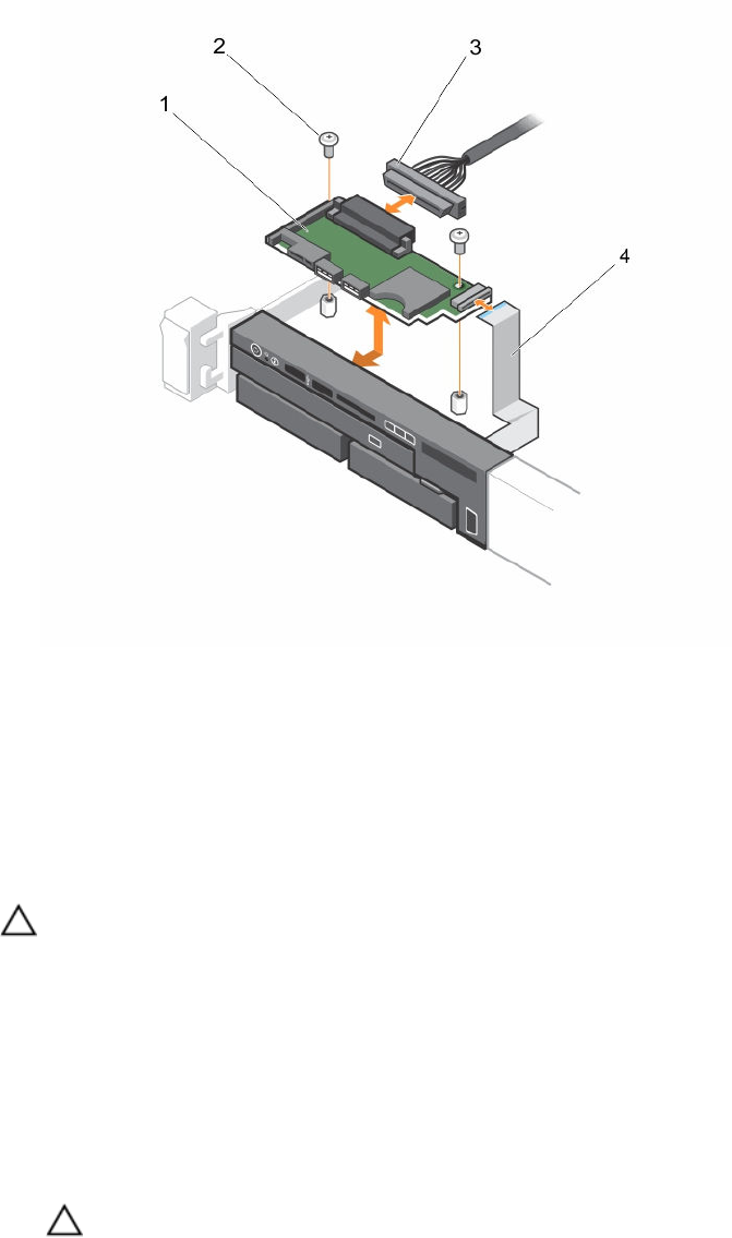
Figure 54. Removing and installing the control panel board
1. control panel board 2. screws (2)
3. control-panel cable 4. display module cable
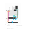
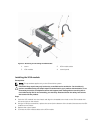
Installing the control panel board–8 hard drive system
Prerequisites
CAUTION: Many repairs may only be done by a certified service technician. You should only
perform troubleshooting and simple repairs as authorized in your product documentation, or as
directed by the online or telephone service and support team. Damage due to servicing that is
not authorized by Dell is not covered by your warranty. Read and follow the safety instructions
that came with the product.
Keep the #2 Philips screwdriver ready.
Steps
1. Align the screw holes on the control panel board with the standoffs on the chassis.
2. Using a #2 Phillips screwdriver, replace the two screws that secure the control panel board to the
chassis.
CAUTION: The display module connector is a ZIF (zero insertion force) connector. Ensure
that the locking tab on the connector is released before removal and insertion. The locking
tab must be engaged after insertion.
3. Connect control panel and display module cables to the control panel board.
119