


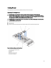

General Memory Module Installation Guidelines
NOTE: Memory configurations that fail to observe these guidelines can prevent your system from starting and
producing any video output, hanging during memory configuration, or operating with reduced memory.
This system supports Flexible Memory Configuration, enabling the system to be configured and run in any valid chipset
architectural configuration. The following are the recommended guidelines for best performance:
• UDIMMs and RDIMMs must not be mixed.
• x4 and x8 DRAM based DIMMs can be mixed. For more information, see Mode-Specific Guidelines.
• A maximum of two UDIMMs can be populated in a channel.
• Up to two quad-rank RDIMMs and up to three dual- or single-rank RDIMMs can be populated per channel.
• Populate DIMM sockets only if a processor is installed. For single-processor systems, sockets A1 to A12 are
available. For dual-processor systems, sockets A1 to A12 and sockets B1 to B12 are available.
• Populate all sockets with white release tabs first, then black, and then green.
• Do not populate the third DIMM socket in a channel with green release tabs, if a quad-rank RDIMM is populated
in the first socket with white release tabs.
• Populate the sockets by highest rank count in the following order - first in sockets with white release levers,
then black, and then green. For example, if you want to mix quad-rank and dual-rank DIMMs, populate quad-
rank DIMMs in the sockets with white release tabs and dual-rank DIMMs in the sockets with black release tabs.
• In a dual-processor configuration, the memory configuration for each processor must be identical. For example,
if you populate socket A1 for processor 1, then populate socket B1 for processor 2, and so on.
• Memory modules of different sizes can be mixed provided that other memory population rules are followed (for
example, 2 GB and 4 GB memory modules can be mixed).
• Populate four DIMMs per processor (one DIMM per channel) at a time to maximize performance.
• If memory modules with different speeds are installed, they will operate at the speed of the slowest installed
memory module(s) or slower depending on system DIMM configuration.
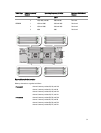
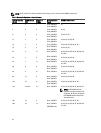
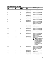
• Populate DIMMs based on the following processor-heat sink configurations.
Processor
Configuration
Processor
Type (in
Watts)
Heat
Sink
Number of DIMMs
Maximum System Capacity Reliability, Availability, and
Serviceability (RAS) Features
Single processor up to 95 W 57 mm 12 12
Single processor 115 W or
130 W
77 mm 10 (Three DIMMs in channels
0 and 3 and two DIMMs in
channels 1 and 2)
8 (Two DIMMs per channel)
Dual processor up to 95 W 57 mm 24 24
Dual processor 115 W or
130 W
77 mm 20 (Three DIMMs in channels
0 and 3 and two DIMMs in
channels 1 and 2)
16 (Two DIMMs per channel)
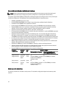
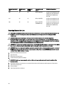
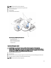
Mode-Specific Guidelines
Four memory channels are allocated to each processor. The allowable configurations depend on the memory mode
selected.
32