


Installing System Components 81
CAUTION: Be careful not to bend any of the pins on the ZIF socket when removing
the processor. Bending the pins can permanently damage the system board.
12
Carefully, lift the processor out of the socket and leave the release lever up
so that the socket is ready for the new processor.
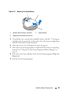
Installing a Processor
CAUTION: Many repairs may only be done by a certified service technician. You
should only perform troubleshooting and simple repairs as authorized in your
product documentation, or as directed by the online or telephone service and
support team. Damage due to servicing that is not authorized by Dell is not covered
by your warranty. Read and follow the safety instructions that came with the
product.
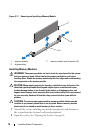
1
Unpack the new processor.
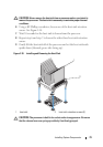
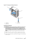
2 Align the
p
rocessor with the
socket keys on t
he ZIF socket. See
Figure 3-19.
CAUTION: Positioning the processor incorrectly can permanently damage the
system board or the processor. Be careful not to bend the pins in the socket.
3
With the release lever on the processor socket in the open position, a
lign
the
p
rocessor with
the
socket
keys
and set the processor lightly in the
socket.
CAUTION: Do not use force to seat the processor. When the processor is
positioned correctly, it engages easily into the socket.
4
Close the processor shield.
5
R
otate the socket release lever down until it snaps into place.
6
Using a clean lint-free cloth, remove the thermal grease from the heat sink.
7
Open the grease packet included with your processor kit and apply thermal
grease evenly to the top of the new processor.
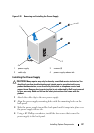
8 Place the heat sink on the processor. See
Figure 3-19
.
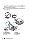
9 Using a #2 Phillips screwdriver, tighten the heat-sink retention screws.
See
Figure 3-18
.
10
Replace the cooling shroud. See "Installing the Cooling Shroud" on
page 67.
11
Replace the expansion-card stabilizer. See "Installing the Expansion-Card
Stabilizer" on page 65.