


41
2
Hardware Installation
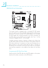
Parallel Connector
X
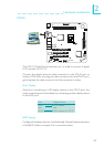
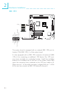
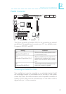
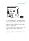
The 25-pin connector at location CN10 is for connecting an external
parallel port. The parallel port connects your PC to a parallel printer.
It supports SPP, ECP and EPP.
Setting
SPP
(Standard Parallel Port)
ECP
(Extended Capabilities Port)
EPP
(Enhanced Parallel Port)
Function
Allows normal speed operation but
in one direction only.
Allows parallel port to operate in
bidirectional mode and at a speed
faster than the SPP’s data transfer
rate.
Allows bidirectional parallel port op-
eration at maximum speed.
2
1
25
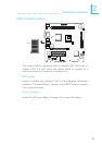
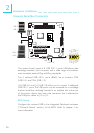
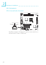
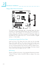
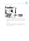
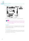
Connecting the Parallel Port Cable
Your parallel port may be mounted on a card-edge bracket. Install
the card-edge bracket to an available slot at the rear of the system
chassis then insert the cable connector onto the parallel connector at
location CN10. Make sure the colored stripe on the ribbon cable is
aligned with pin 1 of the connector.