


Diamond-MM-48-AT User Manual V1.01 Page 14
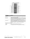
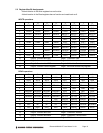
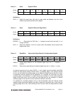
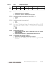
Base + 5 Write Digital I/O Data
Bit No. 7 6 5 4 3 2 1 0
Name DIO3 DIO2 DIO1 DIO0
Definitions:
DIO3 – 0 Digital I/O output data. Only bits in output mode are affected. Any bit in input
mode will ignore data written to this register.
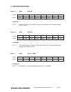
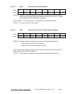
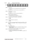
Base + 5 Read Digital I/O Data and Edge Status
Bit No. 7 6 5 4 3 2 1 0
Name DEDGE3 DEDGE2 DEDGE1 DEDGE0 DIO3 DIO2 DIO1 DIO0
Definitions:
DEDGE3 – 0 Edge status for DIO lines: 1 = change occurred since last read, 0 = no
change occurred
DIO3 – 0 Digital I/O readback. If a bit is in output mode, the readback value is equal to the
programmed value.
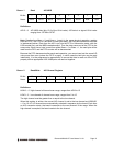
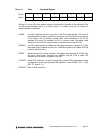
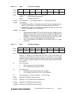
Base + 6 Read/Write Optocoupler Edge Detection Configuration Register
Bit No. 7 6 5 4 3 2 1 0
Name OEN3 OEN2 OEN1 OEN0 POL3 POL2 POL1 POL0
OEN3-0 Enable edge detection on the selected digital input line: 0 = disabled, 1 =
enabled
POL3-0 Select active edge polarity for selected digital input line: 0 = falling, 1 = rising
An interrupt request will occur when OINTE = 1 and a digital input line enabled with OENn
exhibits an edge whose polarity matches POLn (a qualifying edge). If an interrupt request
occurs, and an additional qualifying edge occurs before the digital interrupt flip flop is reset,
no additional interrupt request will be generated. It is possible for more than one line’s
qualifying edge to be detected in a single interrupt (for example if 3 lines exhibit qualifying
edges at the same time), but not more than one edge per line (for example if a second
qualifying edge on the same line occurs before the interrupt is serviced).
It is possible for a qualifying edge to occur in the time between when the interrupt routine
reads the digital input status register and when it resets the interrupt flip flop. In this case the
qualifying edge will be lost, since resetting the flip flop also resets the edge detection status
bits.