


Diamond-MM-48-AT User Manual V1.01 Page 38
14. OPTOCOUPLER OPERATION
Diamond-MM-48-AT contains 4 optocoupler inputs with programmable polarity,
programmable edge detection capability, and interrupt capability on edge detection. These
lines accept inputs up to 28VDC. The transition between logic 0 and 1 occurs at
approximately 1.5VDC and is guaranteed to be 1 at 3VDC or above.
The POL jumper on jumper block J6 selects the logic polarity of the 4 register bits OPTO3-0.
The POL jumper can be read with the POL bit in Base + 8. The POL register bit indicates the
value of an open circuit or logic 0 input signal:
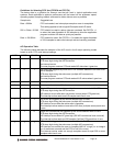
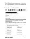
OPTO3-0 readback value
POL jumper POL bit Vin < 1.5VDC Vin > 3VDC
Out 0 0 1
In 1 1 0
To enable edge detection on any optocoupler, set the corresponding OENn bit to 1, and then
select the desired edge polarity with POLn. POLn = 0 selects falling edge, and POLn = 1
selects rising edge. NOTE: The edge polarity is determined with respect to the polarity
selected with the POL jumper. If the POL jumper is in, an input voltage change from 0V to 3V
is considered a falling edge, not a rising edge.
Whenever you read the optocoupler logic level data OPTO3-0 in Base + 7, you also read the
edge status data in the upper 4 bits OEDGE3-0. Reading this register clears the OEDGE3-0
data, so successive reads will show a change in the value of these bits to 0. Note that if an
input toggles in both directions between reads, you will still see the change because the
OEDGEn bit will be 1 even though the logic level remains the same.
The board may also be programmed to generate interrupts when any selected edge occurs.
To enable interrupts on edge detection, set the OINTE bit in Base + 11. when OINTE = 1,
any edge programmed in the above manner will generate an interrupt and set the OINT bit in
Base + 11. The interrupt routine reads the data by reading from Base + 7, and then it clears
the interrupt request by writing a 1 to the CLRO bit in Base + 11.
NOTE: Diamond-MM-48-AT has 4 distinct interrupt circuits that may request interrupt service
independently of each other. A PC/104 bus interrupt request will occur when any one of the
circuits requests service. As long as any circuit is still requesting service, the interrupt request
will stay active. This means that writing to the CLRO bit may not clear the bus interrupt
request even though it clears the specific optocoupler input interrupt request. The interrupt
service routine is responsible for determining which of the three circuits is requesting service
and handling all of them as needed.
Procedure for enabling interrupts on selected edges
1. Select the desired input channel(s) by setting OENn = 1 for each one to be detected.
2. Select the desired edge polarity for each enabled channel by setting POLn appropriately.
NOTE: Steps 1 and 2 are done together with a single write operation to Base + 6.
3. Enable optocoupler interrupts by setting the OINTE bit in Base + 11.
4. When an interrupt occurs, read the edge and logic level data from Base + 7.
5. After reading the edge and logic data, write a 1 to the CLRO bit in Base + 11 to clear the
interrupt request.
6. When interrupt activity is no longer needed, write a 0 to the OINTE bit to disable
optocoupler interrupts.