


Diamond-MM-48-AT User Manual V1.01 Page 39
Tables describing behavior of POL jumper, opto inputs, and edge detection
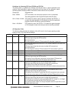
The POL bit is the inverse of the POL pin. Non-inverted inputs means the opto bit is reported
as the inverse of the corresponding input pin, since the opto circuit has a built-in inversion.
Edge detection always operates with respect to the actual input voltage, not the logic. Rising
always means from 0V to 3V, and falling always means from 3V to 0V.
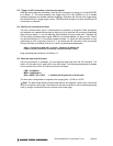
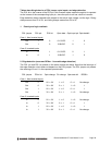
1. Polarity and logic readback
POL jumper POL pin POL bit Opto state Opto input pin Opto databit
Case 1: Non-inverted inputs
Out 1 0 0-1.5VDC 1 0
Out 1 0 3-28VDC 0 1
Case 2: Inverted inputs
In 0 1 0-1.5VDC 0 1
In 0 1 3-28VDC 1 0
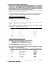
2. Edge detection (assumes OENn = 1 to enable edge detection)
The POL pin and POL bit operate in the same manner as above. Note that the behavior of
the edge detection circuit does not depend on the POL jumper. The POL jumper only affects
the meaning of 0 and 1 in the reported opto data bits.
POL jumper POLn bit Opto change Pin change Opto data bit EDGEn
Case 1: Non-inverted inputs
Out 0 0V -> 3V 1 -> 0 0 -> 1 No change
Out 0 3V -> 0V 0 -> 1 1 -> 0 1
Out 1 0V -> 3V 1 -> 0 0 -> 1 1
Out 1 3V -> 0V 0 -> 1 1 -> 0 No change
Case 2: Inverted inputs
In 0 0V -> 3V 1 -> 0 1 -> 0 No change
In 0 3V -> 0V 0 -> 1 0 -> 1 1
In 1 0V -> 3V 1 -> 0 1 -> 0 1
In 1 3V -> 0V 0 -> 1 0 -> 1 No change