


Diamond-MM-48-AT User Manual V1.01 Page 7
4. BOARD CONFIGURATION
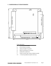
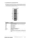
Refer to the Drawing of Diamond-MM-48-AT on page 4 for locations of the configuration
items mentioned here. All configuration except the A/D input range is done with jumper block
J6.
4.1 Base Address
Each board in your system must have a unique I/O address range. The first address in this
range is called the base address. Diamond-MM-48-AT uses an I/O range of 16 bytes. The
base address of this range is set with a portion of jumper block J6, located along the lower
portion of the board near the PC/104 bus connectors. Each of the six jumper locations
marked 10, 9, 8, 7, 6, 5 corresponds to the same-numbered address bit in the board’s 10-bit
I/O address. Bits 4-0 are always 0 for the base address, resulting in a 16-byte I/O address
block located on a 32-byte boundary. A jumper out is equal to a 1, and a jumper in is equal to
a 0. Although any address is selectable, certain locations are reserved or may cause conflicts
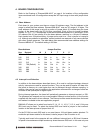
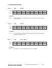
with other system resources. The table below lists recommended base address settings for
Diamond-MM-48-AT. The default setting is 300 Hex.
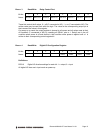
Base Address Jumper Position
Hex Decimal 10 9 8 7 6 5
200 512 In Out In In In In
240 512 In Out In In Out In
280 512 In Out In Out In In
2C0 512 In Out In Out Out In
300 768 (Default) In Out Out In In In
340 832 In Out Out In Out In
380 896 In Out Out Out In In
3C0 960 In Out Out Out Out In
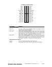
4.2 Interrupt Level Selection
In addition to the base address described above, J6 is used to configure hardware interrupt
activity. Interrupts are used for several functions. They can be used to transfer A/D data from
the board to memory at a rate higher than can be achieved through software sampling. In
addition, they can be used to indicate to the application software when a change of state has
occurred on the optocoupler or digital inputs.
During interrupt operation, the board will periodically generate an interrupt request, or IRQ.
The processor will respond and run a user-supplied interrupt routine function, or the function
supplied with the board’s driver software. The interrupt routine reads the data from the board
and makes it available to the user application program.
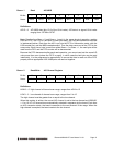
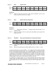
DMM-48-AT allows you to select from levels 15, 14, 12, 11, 10, 9, 7, 6, 5, 4, and 3. Only one
IRQ level may be used. To select the desired IRQ level install a jumper in that number’s
location in the Interrupt area of jumper block J6.
On the PC/104 bus each IRQ level in use must have a 1KΩ pull-down resistor attached. To
enable the pull-down resistor for this board, install a jumper in the R location on J6.
Typically each board in the computer will use a different interrupt level, or IRQ level. However
in special circumstances multiple boards may share the same IRQ level. In this case only one