


Diamond-MM-48-AT User Manual V1.01 Page 24
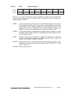
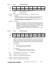
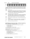
Base + 15 Write Counter/Timer Control Register
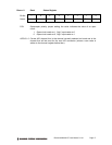
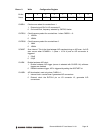
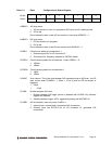
Bit No. 7 6 5 4 3 2 1 0
Name CTRNO LATCH GTDIS GTEN CTDIS CTEN LOAD CLR
This register is used to control the counter/timers. A counter is selected with bit 7, and then a
1 is written to any ONE of bits 6 – 0 to select the desired operation for that counter. The other
bits and associated functions are not affected. Thus only one operation can be performed at
a time.
CTRNO Counter no., 0 or 1
LATCH Latch the selected counter so that its value may be read. The counter must be
latched before it is read. Reading from registers 12-14 returns the most recently
latched value. If you are reading Counter 1 data, read only Base + 12 and Base
+ 13. Any data in Base + 14 will be from the previous Counter 0 access.
GTDIS Disable external gating for the selected counter.
GTEN Enable external gating for the selected counter. If enabled, the associated gate
signal GATE0 or GATE1 controls counting on the counter. If the GATEn signal is
high, counting is enabled. If the GATEn signal is low, counting is disabled.
CTDIS Disable counting on the selected counter. The counter will ignore input pulses.
CTEN Enable counting on the selected counter. The counter will decrement on each
input pulse.
LOAD Load the selected counter with the data written to Base + 12 through Base + 14
or Base + 12 and Base + 13 (depending on which counter is being loaded).
CLR Clear the current counter (set its value to 0).
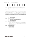
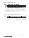
To load a counter: First write the load value to Base + 12 and Base + 13 (for Counter 1) or
Base + 12 through Base + 14 (for Counter 0). Then write a Load command to Base + 15. For
example, to load Counter 0 with the hex value 123456:
♦ Write 0x12 to Base + 14 (these three bytes can be written to in any order)
♦ Write 0x34 to Base + 13
♦ Write 0x56 to Base + 12
♦ Write 0x02 to Base + 15 to load counter 0
To enable counting: Write 0x04 (ctr 0) or 0x84 (ctr 1) to Base + 15.
To stop counting: Write 0x08 (ctr 0) or 0x88 (ctr 1) to Base + 15.
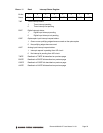
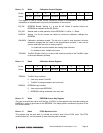
To read a counter: First latch it, then read the value:
♦ Write 0x40 to Base + 15 to latch counter 0 or 0xC0 to latch counter 1
♦ Read LSB from Base +12
♦ Read Middle Byte from Base + 13
♦ Read MSB from Base + 14
♦ Assemble 3 bytes into the current counter value