


Diamond-MM-48-AT User Manual V1.01 Page 23
Page 0: Counter/Timer
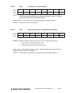
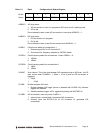
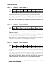
Base + 12 Read/Write Counter/Timer D7 - 0
Bit No. 7 6 5 4 3 2 1 0
Name D7 D6 D5 D4 D3 D2 D1 D0
This register is used for both Counter 0 and Counter 1. It is the LSB for both counters.
When writing to this register, an internal load register is loaded. Upon issuing a Load
command through Base + 15, the selected counter’s LSB register will be loaded with this
value.
When reading from this register, the LSB value of the most recent Latch command will be
returned. The value returned is NOT the value written to this register.
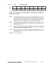
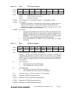
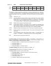
Base + 13 Read/Write Counter/Timer D15 - 8
Bit No. 7 6 5 4 3 2 1 0
Name D15 D14 D13 D12 D11 D10 D9 D8
This register is used for both Counter 0 and Counter 1. It is the MSB for counter 1 and the
middle byte for counter 0.
When writing to this register, an internal load register is loaded. Upon issuing a Load
command through Base + 15, the selected counter’s associated register will be loaded with
this value. For counter 0, it is the middle byte. For counter 1, it is the MSB.
When reading from this register, the associated byte of the most recent Latch command will
be returned. The value returned is NOT the value written to this register.
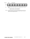
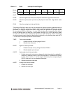
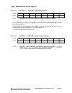
Base + 14 Read/Write Counter/Timer D23 - 16
Bit No. 7 6 5 4 3 2 1 0
Name D23 D22 D21 D20 D19 D18 D17 D16
This register is used for Counter 0 only. Counter 0 is 24 bits wide, while Counter 1 is only 16
bits wide.
When writing to this register, an internal load register is loaded. Upon issuing a Load
command through Base + 15 for Counter 0, the counter’s MSB register will be loaded with
this value. When issuing a Load command for counter 1, this register is ignored.
When reading from this register, the MSB value of the most recent Latch command for
counter 0 will be returned. The value returned is NOT the value written to this register.