


Diamond-MM-48-AT User Manual V1.01 Page 40
15. RELAY OPERATION
Diamond-MM-48-AT contains 8 relays with SPDT (form C) configuration. The relays are
Omron type G6K or equivalent. Note that these relays are actually DPDT (double pole)
relays. The two poles are connected in parallel for lower on resistance and greater current
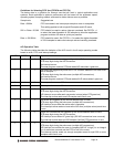
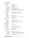
carrying capacity. The relays have the following operating characteristics:
Rated load 0.3A / 125VAC, 1A / 30VDC
Contact material Gold plating over silver
Max operating voltage 125VAC, 60VDC
Max switching capacity 37.5VA, 30W
Min permissible load 10
µA at 10mVDC
Initial contact resistance 100mΩ max
Operate time 3ms max
Release time 3ms max
Bounce time 3ms max
Mechanical life 50,000,000 operations min (at 36,000 operations / hr)
Electrical life 100,000 operations min at rated load (at 1,800 operations / hr)
The relay signals are on connector J4 on the left side of the board. Each relay has 3
contacts: C, NC, and NO. The functions of these contacts are as follows:
Relay N C (N = 0 to 7) Relay output common contact. This contact is always
used with relay output connections.
Relay N NC Relay output normally connected contact. This contact is
connected to the Relay N C contact when power is off or when a 0 is
written to the relay’s control bit in the relay control register. It is
disconnected when power is on and a 1 is written to the relay’s
control bit.
The relay is called “off” when the NC contact is connected to the C
contact (because this represents the power-off state).
Relay N NO Relay output normally open contact. This contact is disconnected
when power is off or when a 0 is written to the relay’s control bit in
the relay control register. It is connected to the Relay N C contact
when power is on and a 1 is written to the relay’s control bit.
The relay is called “on” when the NO contact is connected to the C
contact.
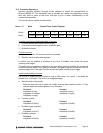
The relays are controlled with a register at Base + 3. Writing a 1 to a relay’s control bit turns
that relay “on”, and writing a 0 to a bit turns the relay “off”. Any combination of relays may be
“on” or “off” at any time under software control. On power-up or system reset, all relays are in
the off position.
The board stores the value written to the relays, and this value may also be read back at
Base + 3. A 1 indicates a relay “on”, and a 0 indicates a relay “off”. This readback value is
only accurate as long as power is maintained to the board.