


Diamond-MM-48-AT User Manual V1.01 Page 41
16. COUNTER/TIMER OPERATION
Diamond-MM-48-AT contains two counter/timers that provide various timing functions,
including A/D timing and user functions. These counters are integrated into the system
controller FPGA.
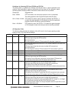
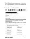
The user interface consists of a 24-bit data register in Base + 12 through Base + 14, an 8-bit
command register in Base + 15, and control bits in several other registers. Using the
command register, the counter can be loaded, cleared, enabled, and disabled, the optional
gate can be enabled and disabled, and the counter value can be latched for reading. Detailed
information on the counter/timer control register bits is provided beginning on page 23.
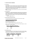
16.1 Counter 0 – A/D Sample Control
Counter 0 is a 24-bit “divide-by-n” counter used for controlling A/D sampling. The counter has
a clock input, a gate input, and an output. The input is a 10MHz or 1MHz clock provided on
the board and selected with bit CKFRQ0 in Base + 9 bit 3. The gate is an optional signal that
can be input on pin 30 of the I/O header J3. If this signal is not used then the counter runs
freely. The output is a positive pulse whose frequency is equal to the input clock divided by
the 24-bit divisor programmed into the counter. The output appears on pin 31 of the I/O
header.
The counter operates by counting down from the programmed divisor value. When it reaches
zero, it outputs a positive-going pulse equal to one input clock period (100ns or 1µs,
depending on the input clock selected by CKFRQ0). It then reloads to the initial load value
and repeats the process indefinitely.
The output frequency can range from 5MHz (10MHz clock, divisor = 2) down to 0.06Hz
(1MHz clock divided by 16,777,215, or 2
24
-1). The output is fed into the A/D timing circuit and
can be selected to trigger A/D conversions when CLKEN = 1 (Base + 9 bit 1) and CLKSEL =
1 (Base + 9 bit 0).
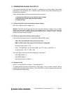
16.2 Counter 1 – Counting/Totalizing Functions
Counter 1 is a 16-bit counter. It may be used as a pulse generator, timed inerrupt generator,
or totalizer/counter.
To use Counter 1 as a pulse generator: The counter is set up as follows: Set CKSEL1 = 0
for on-board clock. If CKFRQ1 = 0, the clock is 10MHz, and if CKFRQ1 = 1, the clock is
100KHz. The optional gate input is on pin 33 of the I/O header J3 and controlled with the
GTEN/GTDIS commands. If pin 33 is left open, the counter will operate continuously. If pin
33 is held low, the counter will not count. The output is on pin 34 of the I/O header. It consists
of a positive pulse that occurs when the counter reaches zero and whose width is one clock
period.
To use Counter 1 as a timed interrupt generator: Set it up as for pulse generator above
and also set TINTE = 1 in Base + 11 bit 3. Each pulse will generate an interrupt on the
PC/104 bus. The interrupt status may be monitored with the TINT bit in Base + 11 bit 7. To
clear the interrupt request, the interrupt service routine writes a 1 to the CLRT bit in base +
11 bit 7. To disable timer interrupts, set TINTE = 0.
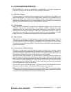
NOTE: Diamond-MM-48-AT has 4 distinct interrupt circuits that may request interrupt service
independently of each other. A PC/104 bus interrupt request will occur when any one of the
circuits requests service. As long as any circuit is still requesting service, the interrupt request
will stay active. This means that writing to the CLRT bit may not clear the bus interrupt
request even though it clears the specific optocoupler input interrupt request. The interrupt
service routine is responsible for determining which of the three circuits is requesting service
and handling all of them as needed.
To use Counter 1 as a totalizer / counter: Set it up as for pulse generator, except Set
CKSEL1 = 1 for external clock. The counter will count rising edges on pin 32 of the I/O
header. The gate input on pin 33 and output on pin 34 operate the same as above.