


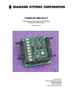

Diamond-MM-48-AT User Manual V1.01 Page 9
5. I/O MAP
5.1 Overview
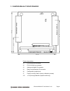
Diamond-MM-48-AT occupies 16 bytes in I/O memory space. A functional list of these
registers is provided below, and detailed register bit definitions are provided on the next page
and the following chapter. The information in chapters 5 and 6 is provided to assist in
understanding the board’s operation and for use by programmers writing their own driver
software. Diamond Systems’ Universal Driver software provides high-level control of the
board’s functionality and will isolate these underlying hardware details for most programmers.
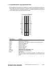
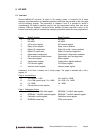
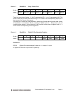
Base + Write Function Read Function
0 D/A LSB A/D LSB
1 D/A MSB A/D MSB
2 A/D channel register A/D channel register
3 Relay control register Relay control readback
4 Digital I/O configuration Digital I/O config + status readback
5 Digital I/O output data Digital I/O input and edge data
6 Optocoupler configuration Optocoupler configuration readback
7 D/A channel and update control Optocoupler input and edge data
8 Command register Status register
9 Configuration register Configuration register readback
10 FIFO control register FIFO status register
11 Interrupt control register Interrupt status register
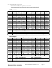
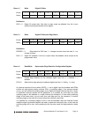
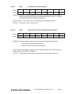
Addresses 12-15 form a window into 2 4-byte pages. The page is selected with a bit in
register 10.
Page 0: counter/timers
12 Ctr 0 and Ctr 1 LSB Ctr 0 and Ctr 1 MSB
13 Ctr 0 CSB (center byte) / Ctr 1 MSB Ctr 0 CSB / Ctr 1 MSB
14 Ctr 1 MSB Ctr 1 MSB
15 Counter/timer control register ---
Page 1: Calibration Control
12 EEPROM / TrimDAC data register EEPROM / TrimDAC data register
13 EEPROM / TrimDAC address register EEPROM / TrimDAC address register
14 Calibration control register Calibration status register
15 EEPROM access key FPGA code version