


Prometheus CPU User Manual V1.44 Page 15
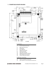
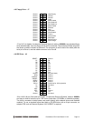
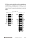
4.11 PC/104 Bus Connectors
The PC/104 bus is essentially identical to the ISA Bus except for the physical design. It specifies
two pin and socket connectors for the bus signals. A 64-pin header J1 incorporates the 62-pin 8-
bit bus connector signals, and a 40-pin header J2 incorporates the 36-pin 16-bit bus connector
signals. The additional pins on the PC/104 connectors are used as ground or key pins. The
female sockets on the top of the board enable stacking another PC/104 board on top of the board,
while the male pins on the bottom enable the board to plug into another board below it.
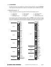
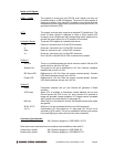
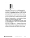
In the pinout figures below, the tops correspond to the left edge of the connector when the board
is viewed from the primary side (side with the CPU chip and the female end of the PC/104
connector) and the board is oriented so that the PC/104 connectors are along the bottom edge of
the board.
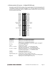
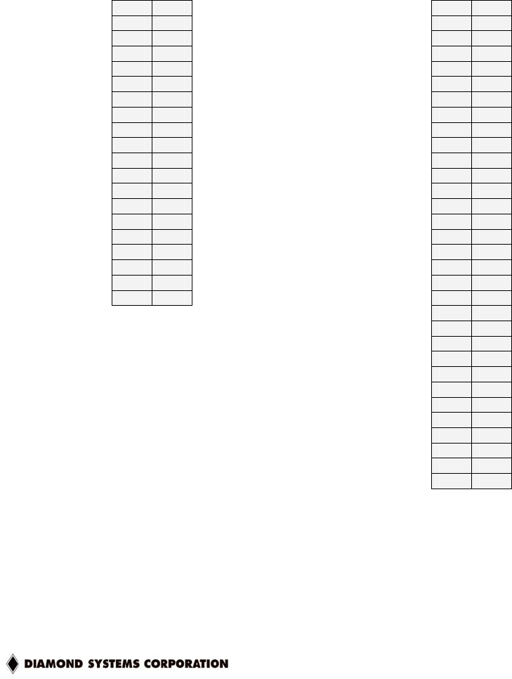
View from Top of Board
J2: PC/104 16-bit bus connector J1: PC/104 8-bit bus connector
Ground D0 C0 Ground IOCHCHK- A1 B1 Ground
MEMCS16- D1 C1 SBHE- SD7 A2 B2 RESET
IOCS16- D2 C2 LA23 SD6 A3 B3 +5V
IRQ10 D3 C3 LA22 SD5 A4 B4 IRQ9
IRQ11 D4 C4 LA21 SD4 A5 B5 -5V
IRQ12 D5 C5 LA20 SD3 A6 B6 DRQ2
IRQ15 D6 C6 LA19 SD2 A7 B7 -12V
IRQ14 D7 C7 LA18 SD1 A8 B8 0WS-
DACK0- D8 C8 LA17 SD0 A9 B9 +12V
DRQ0 D9 C9 MEMR- IOCHRDY A10 B10 Key (pin cut)
DACK5- D10 C10 MEMW- AEN A11 B11 SMEMW-
DRQ5 D11 C11 SD8 SA19 A12 B12 SMEMR-
DACK6- D12 C12 SD9 SA18 A13 B13 IOW-
DRQ6 D13 C13 SD10 SA17 A14 B14 IOR-
DACK7- D14 C14 SD11 SA16 A15 B15 DACK3-
DRQ7 D15 C15 SD12 SA15 A16 B16 DRQ3
+5V D16 C16 SD13 SA14 A17 B17 DACK1-
MASTER- D17 C17 SD14 SA13 A18 B18 DRQ1
Ground D18 C18 SD15 SA12 A19 B19 Refresh-
Ground D19 C19 Key (pin cut) SA11 A20 B20 SYSCLK
SA10 A21 B21 IRQ7
SA9 A22 B22 IRQ6
SA8 A23 B23 IRQ5
SA7 A24 B24 IRQ4
SA6 A25 B25 IRQ3
SA5 A26 B26 DACK2-
SA4 A27 B27 TC
SA3 A28 B28 BALE
SA2 A29 B29 +5V
SA1 A30 B30 OSC
SA0 A31 B31 Ground
Ground A32 B32 Ground