


Prometheus CPU User Manual V1.44 Page 41
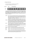
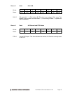
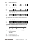
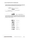
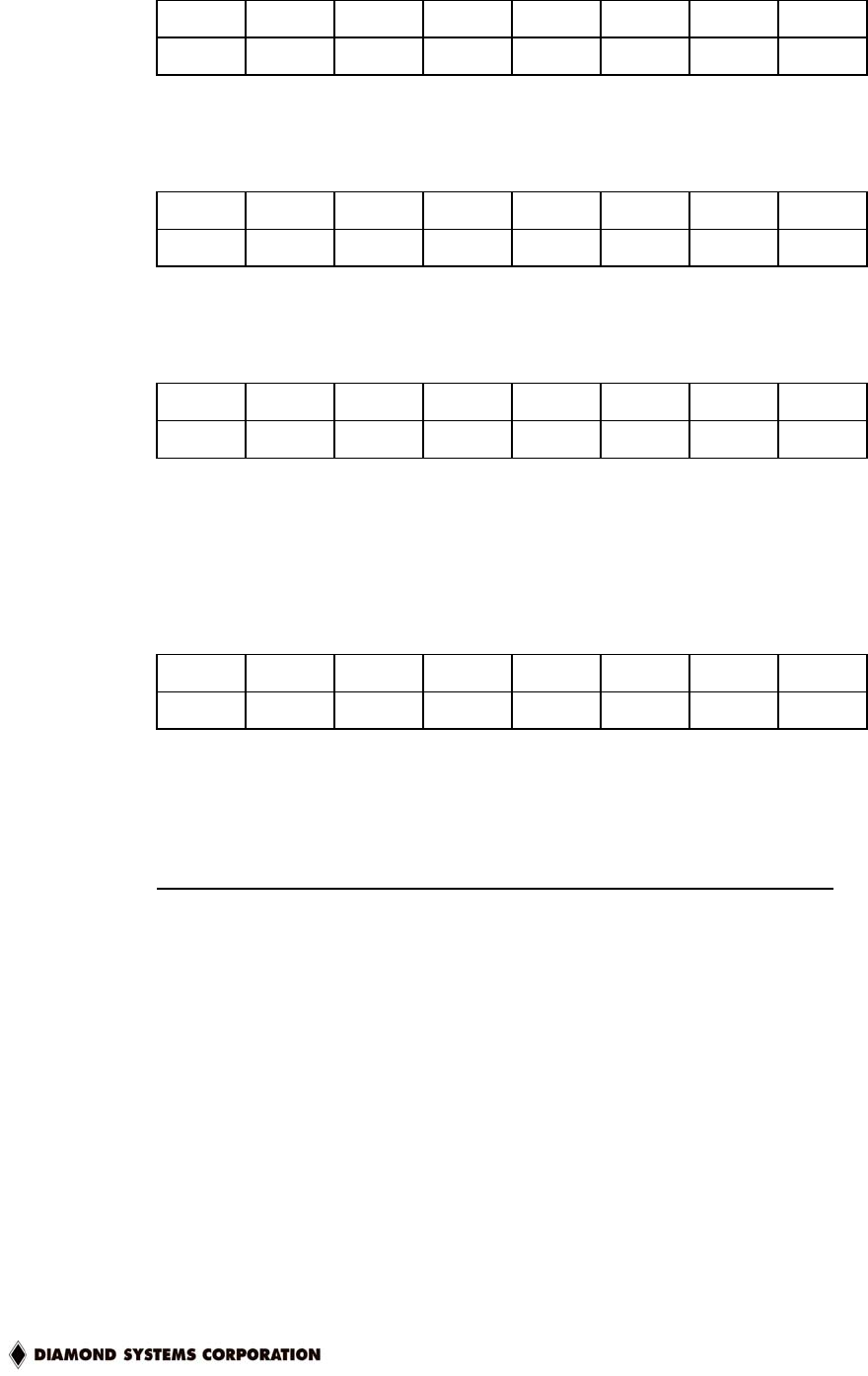
Base + 8 Read / Write Digital I/O Port A
Bit No. 7 6 5 4 3 2 1 0
Name A7 A6 A5 A4 A3 A2 A1 A0
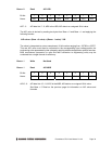
Base + 9 Read / Write Digital I/O Port B
Bit No. 7 6 5 4 3 2 1 0
Name B7 B6 B5 B4 B3 B2 B1 B0
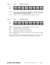
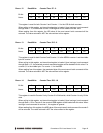
Base + 10 Read / Write Digital I/O Port C
Bit No. 7 6 5 4 3 2 1 0
Name C7 C6 C5 C4 C3 C2 C1 C0
These 3 registers are used for digital I/O. The direction of each register is controlled by bits in the
register below.
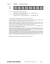
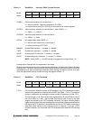
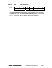
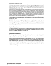
Base + 11 Read / Write Digital I/O Control Register
Bit No. 7 6 5 4 3 2 1 0
Name DIOCTR X X DIRA DIRCH X DIRB DIRCL
The bit assignments of this register are designed to be compatible with the 82C55 chip’s control
register.
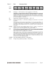
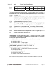
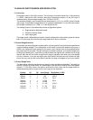
DIOCTR Selects counter I/O signals or digital I/O lines C4-C7 on pins 21-24 of J14:
Pin No. DIOCTR = 1 DIOCTR = 0 Pin direction for DIOCTR = 0
21 C4 Gate 0 Input
22 C5 Gate 1 Input
23 C6 Clk 1 Input
24 C7 Out 0 Output
NOTE: If DIOCTR = 0, then the pin direction is as shown above. If DIOCTR = 1 then the pin
direction is controlled by DIRCH.
This bit resets to 1.
DIRA Port A direction. 0 = output, 1 = input
DIRB Port B direction: 0 = output, 1 = input
DIRCH Port C bits 7-4 direction: 0 = output, 1 = input
DIRCL Port C bits 3-0 direction: 0 = output, 1 = input